
SPD thermal stability is about safe behaviour under abnormal heat, not a claim that a surge protective device can tolerate any overvoltage. A healthy SPD limits short transient surges. If sustained voltage stress drives an internal voltage-limiting element into dangerous heating, the device needs a controlled response.
That response can be stable operation under the specified test conditions or disconnection of the failed protection path. Both outcomes matter. A disconnected SPD may leave the circuit energised, but it no longer protects that circuit from surges and must be replaced.
What SPD thermal stability means
SPD thermal stability means that, after operating-duty heating under specified voltage and ambient conditions, the device temperature falls with time while the SPD remains energised. The result shows controlled behaviour for that stated test setup. It does not mean that every SPD will survive every sustained overvoltage or every installation fault.
The word “specified” carries much of the meaning. The result applies to the tested product configuration, its maximum continuous operating voltage (Uc), and the stated conditions. Changing the voltage rating, protection mode, internal design, or system arrangement can change the question being tested.
For low-voltage power SPDs, IEC 61643-11:2025 is the international requirements-and-test-methods framework engineers use when reviewing performance documentation. A technical submittal should identify the exact product and configuration covered by that documentation, rather than relying on a generic statement about a product family.
Figure 1 shows the two paths an SPD can take after abnormal heating: controlled thermal behaviour under the stated conditions, or disconnection followed by replacement.
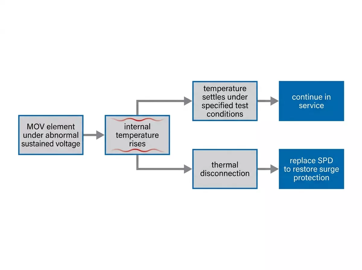
Figure 1 — Thermal behaviour path from MOV heating to controlled operation or thermal disconnection.
Why a transient surge and sustained overvoltage create different risks
A surge and a sustained overvoltage are not the same electrical event. A voltage-limiting SPD is designed to divert transient energy that rises and decays quickly. A longer abnormal voltage can keep the limiting element conductive for long enough to create continuous internal heating.
| Condition | What the SPD is expected to do | Main question |
| Transient surge | Limit voltage and divert the surge energy within its declared duty | Can the SPD withstand its specified surge current? |
| Sustained overvoltage | Remains exposed beyond normal continuous conditions for longer | Does internal temperature stabilise, or does the failed path disconnect safely? |
Metal-oxide varistors (MOVs) are widely used in voltage-limiting SPDs. Under normal system voltage, an MOV draws very little current. Under an abnormal sustained voltage, MOV conduction and heat can keep increasing instead of ending with the transient event. The wider causes and effects belong in our guide to overvoltage protection; the point here is narrower: thermal stability looks at the safe boundary when heat becomes the problem.
What thermal overload protection does inside an SPD
Thermal overload protection is intended to separate an overheating SPD from its protection path before internal heat develops into a more hazardous failure. The exact mechanism varies by product design. Do not assume that every SPD uses the same thermal disconnector, trip point, or end-of-life behaviour.
Three functions are often confused in panel specifications:
- Surge limiting is the normal protective function while the SPD is healthy.
- A visual indicator or remote contact reports that a module needs attention.
- An upstream fuse or circuit breaker manages the relevant fault-current coordination outside the SPD.
A red status window or remote alarm is information, not a repair. Once a thermal protection path has disconnected an SPD, the branch can remain powered while the surge protection is gone. The installer must follow the manufacturer’s replacement instructions and confirm the system is protected again.
Thermal disconnection also does not replace upstream protection coordination. The correct external device depends on the SPD design, prospective short-circuit current, installation arrangement, and manufacturer documentation. Our comparison of SPD vs circuit breaker explains why one device cannot be treated as a substitute for the other.
What an SPD thermal stability test checks
An SPD thermal stability test evaluates one stated product configuration under stated voltage and ambient conditions. It is not a quick on-site pass/fail check. The test examines whether the device reaches controlled thermal behaviour or moves to its intended safe-disconnection response under the applicable conditions.
The test asks:
- Does temperature fall after the operating-duty heating condition, or continue rising?
- Does the protective path remain electrically controlled or disconnect in the intended way?
- Does the result match the actual Uc, configuration, and intended power system of the device being specified?
The test report matters more than a brochure phrase such as “thermal protection included.” Ask for documentation that identifies the exact part number or defined family variant. Avoid treating one model’s report as evidence for a differently rated, differently wired, or differently configured SPD.
No universal trip time, enclosure temperature, or arc statement belongs in a general article. Those details depend on the applicable standard procedure and the product under test. Product-specific test evidence is where an engineer should look for those limits.
How to verify thermal stability without duplicating a type test
A multimeter can support limited troubleshooting when the device instructions permit it, but it cannot prove SPD thermal stability. It cannot reproduce the applied voltage, thermal conditions, protective operation, or fault-current coordination used in a type test.
Insulation-resistance testing has a different purpose. It can be part of a controlled installation test, but it does not establish that an SPD will regulate its internal temperature or disconnect safely during abnormal sustained stress. Follow the SPD manufacturer’s instructions before connecting any test instrument to the device.
Figure 2 separates the evidence a type test can produce from the limited checks available during field maintenance.
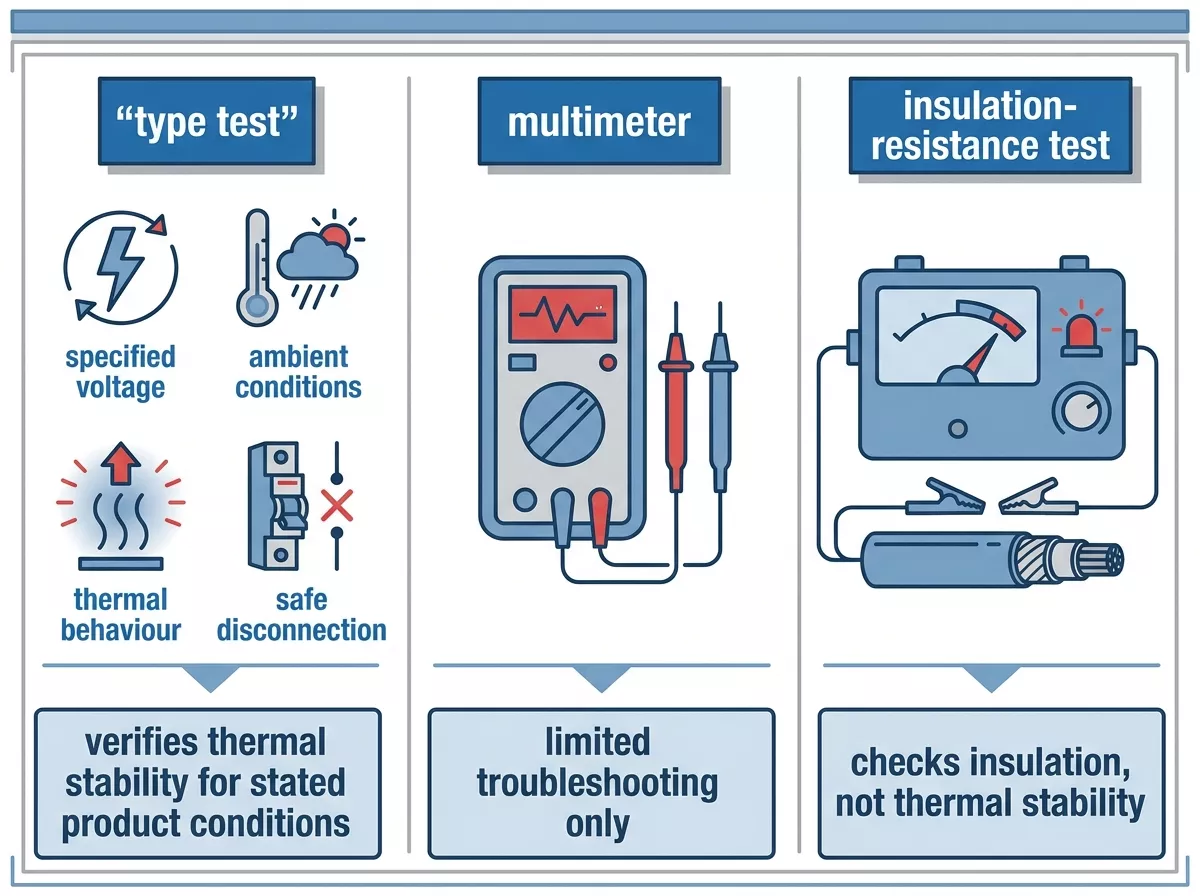
Figure 2 — Type-test evidence and field checks answer different SPD questions.
Before specifying or approving an SPD, check these five points:
- IEC 61643-11 documentation that applies to the exact model and configuration.
- An appropriate Uc for normal system voltage and credible temporary-overvoltage conditions.
- The declared end-of-life indication and replacement procedure.
- Required coordination with upstream fuses or circuit breakers.
- Compatibility with the installation arrangement and earthing system.
The second point deserves more than a nameplate glance. A higher surge-current figure does not automatically answer whether the chosen Uc suits the system’s abnormal-voltage conditions. Review the complete application data before substituting one SPD for another.
Figure 3 turns the documentation check into a short sequence that procurement and engineering teams can use before approving an SPD.
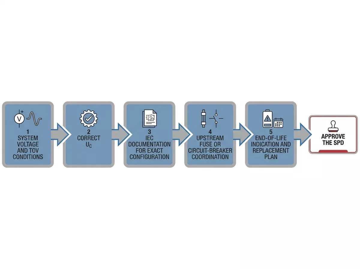
Figure 3 — SPD review path before specification or replacement.
What to do after an SPD indicates end of life
Treat an end-of-life indication as a maintenance task, not a cosmetic warning. Use the site’s isolation procedure, inspect the SPD and its installation, and identify whether abnormal voltage, repeated surges, a wiring issue, or the expected end of service life could explain the event.
Replace the module or device with the correct specification, then restore the protective function in line with the manufacturer’s instructions. A pluggable module can simplify the physical replacement on compatible products, but it does not remove the need to check the underlying cause. Our guide to SPD aging and replacement covers the wider inspection and replacement process.
[Image: thor-spd-fault-indicator-status-window.jpg]
Figure 4 — Placeholder for an in-house comparison of an SPD red fault window and normal status window.
alt text: SPD visual fault indicator showing red end-of-life status beside normal condition
FAQ
What does SPD thermal stability mean?
SPD thermal stability means that a device’s temperature falls with time after operating-duty heating while it remains energised under specified conditions. It is a test-result concept tied to the particular SPD configuration, Uc, and ambient conditions. It is not a guarantee that an SPD can withstand any sustained overvoltage.
Does thermal overload protection keep an SPD working after it trips?
No. Thermal overload protection is intended to remove an overheating SPD from its protection path. The circuit can remain energised after that action, but the SPD no longer provides surge protection until the correct module or device is replaced.
Can a multimeter test SPD thermal stability?
No. A multimeter can help with limited checks when the manufacturer permits them, but it cannot recreate the voltage, heating, and coordination conditions of an SPD thermal stability test. Use the product’s test documentation and installation instructions for verification.
What is the difference between an SPD thermal test and an insulation-resistance test?
An SPD thermal test checks controlled thermal behaviour or safe disconnection under defined electrical conditions. An insulation-resistance test checks insulation properties in an installation context. Neither test should be substituted for the other.
Why does *Uc* matter when selecting an SPD?
Uc is the maximum continuous operating voltage assigned to the SPD. Selecting Uc without considering normal system voltage and credible abnormal-voltage conditions can expose the SPD to stress outside the intended application. The correct value comes from the power-system arrangement and the manufacturer’s application data.
Thor Electric AC SPDs
Thor Electric supplies AC SPD ranges covering Type 1, Type 2, and combined Type 1+2 applications, with IEC 61643-11 and EN 61643-11 conformity stated for the listed product families. Pluggable-module product families include visual fault indication and optional remote indication, which can support planned maintenance after a status change. Share the system voltage, earthing arrangement, and required SPD configuration through the Thor Electric contact page for selection support.