
SPD backup protection has two jobs at different times. During a surge, the fuse or circuit breaker must carry the impulse long enough for the surge protective device to divert it. If the SPD later develops a sustained power-frequency fault, internal or external disconnection must remove that fault safely.
That timing explains a result that often looks suspicious: an SPD can be damaged while its upstream fuse remains intact. IEC 61643-12:2020 Annex N supplies useful SPD backup protection guidance, but its fuse and circuit-breaker tables are not universal product-selection data.
Why can the SPD fail while the fuse stays intact?
An SPD and its backup device respond to different electrical events. The SPD reacts to transient voltage and conducts surge current for microseconds. A fuse or circuit breaker responds to overcurrent according to its own time-current and energy characteristics.
During the initial impulse, unwanted operation of the backup device would disconnect the SPD just when it is needed. The fuse or breaker therefore needs enough impulse withstand to let the surge reach the SPD. The SPD then limits the voltage and diverts current toward the protective conductor.
The second stage starts only if the SPD develops a sustained fault. Its internal thermal disconnector may isolate a degraded protective component. If a short circuit or power-frequency follow current remains, the permitted external fuse or circuit breaker must interrupt it. The difference between an SPD and a circuit breaker is easiest to understand when these two stages are kept separate.
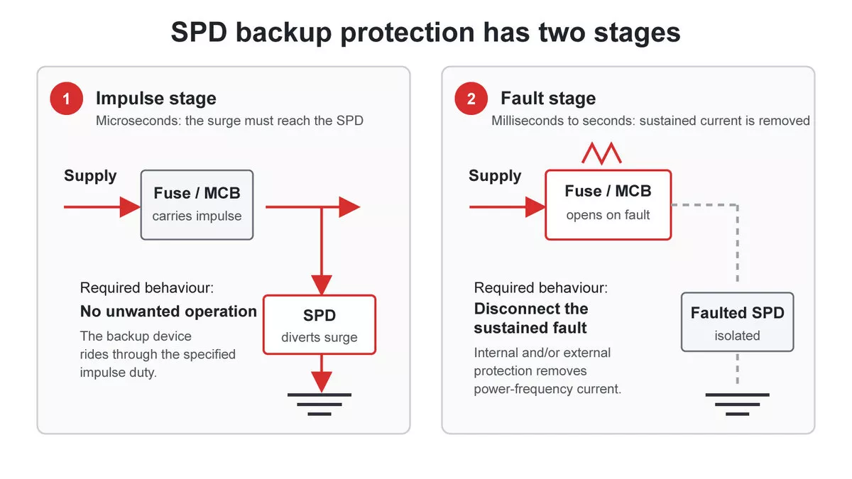
Figure 1 — SPD backup protection during the impulse stage and the later fault stage.
A fuse that remains intact during the first stage may be doing exactly what the coordination requires. Its condition alone says little about whether the SPD experienced excessive impulse energy, a temporary overvoltage, incorrect system voltage, or a product defect.
How IEC table N.1 supports SPD backup protection
IEC 61643-12:2020 Annex N Table N.1 gives examples of gG fuse-link withstand during complete SPD preconditioning and operating-duty tests. The table relates the fuse’s rated current to two SPD test currents:
- In, the nominal discharge current with an 8/20 microsecond waveform;
- Iimp, the impulse discharge current with a 10/350 microsecond waveform.
These are selected examples from the table:
| gG fuse rating | Maximum *In*, 8/20 | Maximum *Iimp*, 10/350 |
| 80 A | 25 kA | 5.6 kA |
| 160 A | 57 kA | 13 kA |
| 200 A | 72 kA | 16 kA |
| 315 A | 123 kA | 28 kA |
To use the table as a preliminary withstand check, find a value in the relevant current column that is at least as high as the SPD rating. The fuse rating on the same row is the smallest listed example with that withstand. For an SPD with In of 20 kA, the 63 A row reaches only 19 kA, while the 80 A row reaches 25 kA. The table therefore points to 80 A gG as the first listed rating that passes this particular impulse-withstand check.
Table N.1 does not use Imax. A Type 2 SPD marked In 20 kA and Imax 40 kA must be checked against the 20 kA In value. The 40 kA Imax value belongs to a different test duty. The guide to reading SPD ratings explains why In, Imax and Iimp describe different test duties.
The maximum backup fuse for an individual SPD remains a separate product declaration. Table N.1 describes the impulse withstand of gG fuse-links; product fault protection requires another check.
The two limits that decide a backup fuse
Practical SPD backup protection sits between two limits. The protective device needs enough impulse withstand to avoid unwanted operation during the SPD duty test. It must also remain within the maximum backup-device rating and characteristics declared by the SPD manufacturer.
The first limit is about surge continuity. IEC Table N.1 helps with that side for gG fuse-links. The second limit is about safely clearing a fault in the tested SPD assembly. It comes from the SPD datasheet, installation instructions or coordination documentation.
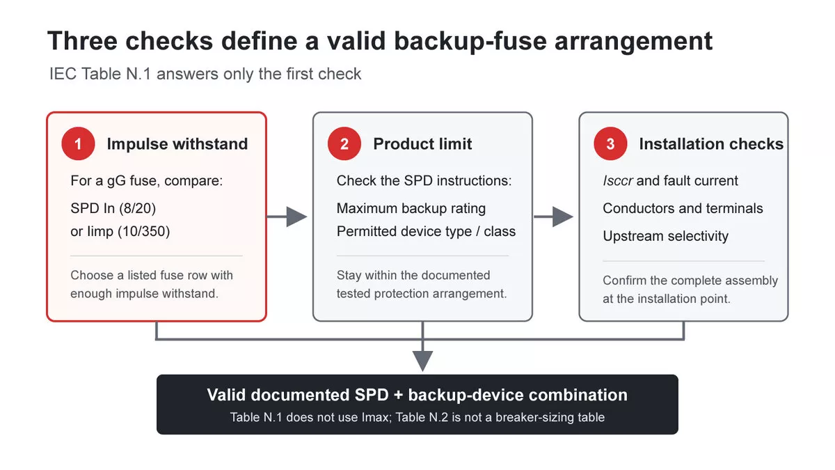
Figure 2 — The checks that define a valid SPD backup-fuse selection.
IEC 60364-5-53 Clause 534.4.5 requires SPD overcurrent protection to follow the manufacturer’s instructions. An external overcurrent protective device is selected for conductor protection and surge capability without exceeding the manufacturer’s stated maximum protection.
The ampere value is only one part of the decision. A valid arrangement must also satisfy:
- the specified fuse class or permitted breaker series and characteristic;
- the SPD assembly’s short-circuit current rating, often declared as Isccr;
- the prospective short-circuit current at the installation point;
- branch-conductor and terminal requirements;
- selectivity with upstream protective devices when continuity matters.
Suppose Table N.1 indicates that 80 A gG is the first listed fuse able to ride through an SPD’s In. If that SPD’s instructions state a maximum backup fuse of 125 A gG, a suitable rating may exist between those two checks. If the manufacturer’s maximum is below the impulse-withstand result, the table has exposed a coordination problem rather than supplied permission to install a larger fuse. The manufacturer must identify a valid arrangement.
Why SPD backup protection needs separate breaker data
Fuse and breaker ratings use amperes, but equal ampere values do not mean equal impulse behaviour. Table N.1 applies to gG fuse-links. MCB and MCCB selection requires separate coordination data.
IEC 61643-12 Annex N Table N.2 gives a qualitative comparison of the external disconnector technologies investigated at 230/400 V:
| Behaviour | General finding in Table N.2 | Selection consequence |
| 8/20 surge withstand | Breakers generally showed higher withstand than same-current fuses; the reported difference was larger at 80 A and below | A fuse value gives no MCB rating because the finding is comparative, not a pairing table |
| 10/350 lightning-current withstand | No general statement is possible; performance depends strongly on breaker technology | Use tested manufacturer coordination data for Type 1 duty |
| Added voltage drop in the SPD branch | At lower ratings, breakers generally added more voltage drop than fuses; the relationship changed as rating increased | The external device can affect the effective protective level and must be evaluated as part of the assembly |
The short duration of an 8/20 impulse helps explain the first result. A fuse element responds to deposited I²t energy. A circuit breaker needs its thermal or magnetic release and mechanical contacts to complete an operation. A very short impulse may pass before that sequence opens the circuit. Breaker performance still depends on its technology, particularly under the longer and more energetic 10/350 waveform.
Use the exact MCB or MCCB series, trip characteristic and rating stated in the SPD coordination documentation. If the documentation lists only a maximum gG fuse, request the breaker pairing instead of assuming that the same ampere rating is equivalent.
A 20/40 kA Type 2 SPD behind a 160 A gG fuse
Consider an AC Type 2 SPD marked In 20 kA and Imax 40 kA at a main distribution board. Its upstream device is a 160 A gG fuse. The SPD is visibly damaged after an event, while the fuse remains intact.
Table N.1 lists a maximum In of 57 kA for a 160 A gG fuse. That value is well above the SPD’s 20 kA In. The fuse can therefore remain intact during an impulse that reaches or exceeds the Type 2 SPD’s normal test duty. The 40 kA Imax marking is outside this lookup because Table N.1 uses In and Iimp.
An intact fuse is therefore plausible, but the explanation is not a failure diagnosis. The next SPD backup protection question is whether the product documentation permits 160 A gG as its upstream or branch protection. If its maximum is 125 A gG, the installed arrangement exceeds the declared limit. If 160 A gG is permitted, the protection rating alone leaves the site’s surge exposure unresolved.
At a main distribution board, the need for Type 1 or Type 1+2 protection depends on conditions such as an external lightning protection system, possible partial lightning current at the installation boundary and the applicable installation design. Where 10/350 duty is required, use an SPD with an appropriate Iimp rating. The Type 1 and Type 2 test duties need to match the installation.
The damage investigation should then check the system voltage and SPD Uc, temporary overvoltage or neutral faults, connection condition, conductor routing, available short-circuit current, Isccr, internal disconnector condition and evidence of the electrical event. A burned enclosure requires this additional evidence before the mechanism can be identified.
How to specify SPD backup protection
A defensible SPD backup protection decision can be recorded in six steps:
- Identify the required SPD test class and the relevant In or Iimp rating.
- Read the manufacturer’s permitted upstream or branch protective-device data, including device type, class, series and maximum rating.
- For a gG fuse, use IEC Table N.1 as an impulse-withstand check, using In rather than Imax.
- For an MCB or MCCB, use a tested pairing. IEC Table N.2 supplies qualitative behaviour guidance only.
- Check Isccr, prospective short-circuit current, breaking capacity, conductors, terminals and selectivity.
- Record whether protection is internal, supplied by the existing upstream device, or installed separately in the SPD branch.
The resulting SPD backup protection record also makes a later failure review more useful. It separates three questions that are often mixed together: whether the backup device carried the impulse, whether it could disconnect a sustained fault, and whether the SPD class matched the surge exposure.