Quick Comparison: Type 1, Type 2, and Type 3 SPD at a Glance
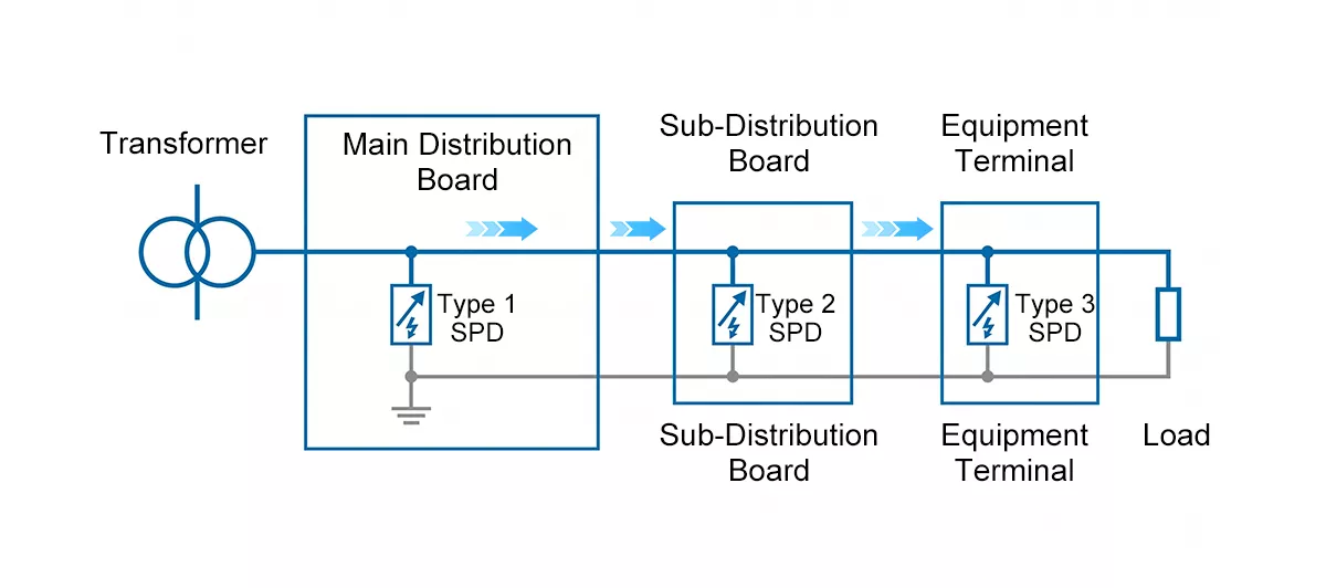
Figure 1: Installation positions of Type 1, Type 2, and Type 3 SPDs in a low-voltage system per IEC 61643-11.
Each type installs at a specific point in the distribution chain.
Type 1, Type 2, and Type 3 SPDs are three classifications defined in IEC 61643-11, each covering a different position in the electrical system and a different level of surge energy.
The classification is not about quality or price — it is about where the device installs and what surge waveform it is designed to handle.
| Type 1 | Type 2 | Type 3 | Type 1+2 | |
| Also called | Class I SPD | Class II SPD | Class III SPD | Combined arrester |
| Test waveform | 10/350µs | 8/20µs | 1.2/50µs + 8/20µs | 10/350µs + 8/20µs |
| Key rating | Iimp | In / Imax | Uoc / Isc | Iimp + Imax |
| Typical rating | 15–50kA (Iimp) | 20–60kA (Imax) | – | Iimp 12.5kA / Imax 50kA |
| Installation point | Main board / service entrance | Sub-distribution board | At or near protected equipment | Main or sub-distribution board |
| Surge threat | Direct lightning current from LPS or overhead lines | Induced surges, switching transients | Residual low-energy transients | Both direct and induced surges |
| Mandatory when | Building has external LPS or overhead supply | Every distribution board | Sensitive equipment present | Space-constrained or retrofit |
| Thor model | TRS-A15 / A25 / A50 | TRS4 series | – | TRS5-B+C |
Why the Waveform Defines Everything: 10/350µs vs 8/20µs
The most common mistake in SPD specification is treating Type 1 and Type 2 as interchangeable — just different ratings of the same thing. They are not. The difference comes down to the test waveform, and the waveform determines how much energy the device must survive.
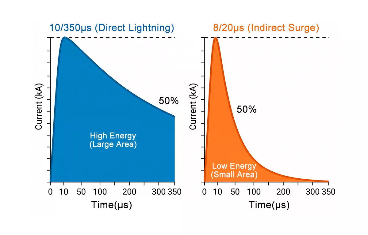
Figure 2: The 10/350µs waveform (Type 1) carries 10–20× more total energy than the 8/20µs waveform (Type 2) at the same peak current. The shaded area represents total energy — this is why Type 1 and Type 2 SPDs are not interchangeable.
The 10/350µs waveform simulates direct lightning current. It rises to peak in 10 microseconds and decays over 350 microseconds. That long tail is the problem — at the same peak current, a 10/350µs impulse carries roughly 10 to 20 times more total energy than an 8/20µs impulse. This is the waveform used to test Type 1 SPDs.
The 8/20µs waveform simulates induced surges and switching transients. It rises faster and decays much sooner, delivering far less total energy at the same peak. This is the waveform used to test Type 2 and Type 3 SPDs.
If a Type 2 SPD is installed where a Type 1 is required and a direct lightning event occurs, the Type 2 absorbs 10 to 20 times the energy it was designed for. The result is not degraded performance — it is immediate destructive failure.
This is also why Iimp and Imax are not the same parameter and cannot be compared directly:
- Iimp — lightning impulse current, tested at 10/350µs. Applies to Type 1 SPDs only.
- Imax — maximum discharge current, tested at 8/20µs. Applies to Type 2 and Type 3 SPDs.
Note: A supplier quoting Imax figures for a device claimed to be Type 1 is not supplying a real Type 1 SPD. Always ask for Iimp test data with the 10/350µs waveform — that is the only valid proof of Type 1 compliance under IEC 61643-11.
Type 1 SPD: When It’s Required and Where It Installs
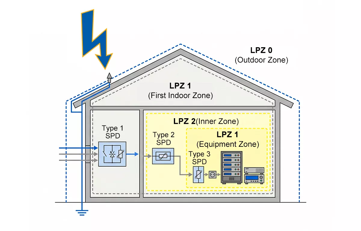
Figure 3: Lightning Protection Zones (LPZ) per IEC 62305-4. Type 1 SPD installs at the LPZ 0→1 boundary where direct lightning current enters the building. Type 2 SPD installs at LPZ 1→2 to handle residual energy.
Type 1 SPD is the first line of defence against direct lightning current. It installs at the main distribution board or service entrance and intercepts high-energy surge current before it travels into the internal electrical system.
Under IEC 60364-5-53 and IEC 62305-4, a Type 1 SPD is mandatory in two situations:
- The building has an external lightning protection system (LPS) with air terminals and down conductors per IEC 62305-3.
- The building is supplied by overhead power lines, where indirect lightning strike near the line injects surge current directly into the service entrance.
In both cases, the SPD must sit at the LPZ 0→1 boundary — where the external lightning protection zone meets the first protected zone inside the building. If neither condition applies, Type 1 is not mandatory, though it may still be specified for critical infrastructure.
Technology note: Type 1 SPDs require a component capable of handling the sustained energy of a 10/350µs event. Thor’s TRS-A series uses a graphite gap surge arrester — a spark gap technology that ionises under high voltage to create a low-impedance discharge path, diverting lightning impulse current to earth before it reaches downstream equipment.
| Model | Iimp (10/350µs) | Up | Uc | Standard |
| TRS-A15 | 15kA | ≤2.0kV | 275V AC | IEC 61643-11/T1 |
| TRS-A25 | 25kA | ≤2.2kV | 275V AC | IEC 61643-11/T1 |
| TRS-A50 | 50kA | ≤2.5kV | 275V AC | IEC 61643-11/T1 |
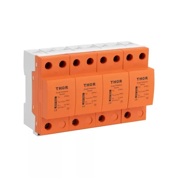
Figure 4: Thor TRS-A50 Type 1 SPD. Graphite gap technology, rated Iimp 50kA, certified to IEC 61643-11/T1.
Important: A Type 1 SPD does not provide complete protection on its own. Its Up values (2.0–2.5kV) are higher than the impulse withstand voltage of most sensitive downstream equipment. A coordinated Type 2 SPD downstream is always required.
Type 2 SPD: Why Every Distribution Board Needs One
If there is one SPD type that applies to virtually every low-voltage installation, it is Type 2. Every distribution board is exposed to switching transients — voltage spikes generated inside the building every time a large inductive load switches on or off. Motors, compressors, variable frequency drives (VFDs), and contactors all produce transient overvoltages as a normal part of operation.
A Type 2 SPD uses metal oxide varistor (MOV). technology to clamp transient voltage — when a surge exceeds the clamping threshold, the MOV’s resistance drops from megaohms to milliohms in under 25 nanoseconds.
Even in buildings supplied by underground cables, a Type 2 SPD at the main distribution board is still required. Underground supply eliminates the need for Type 1, but does nothing to address internally generated switching transients.
| Model | In (8/20µs) | Imax (8/20µs) | Up | Uc |
| TRS4-D10 | 5kA | 10kA | ≤0.7kV | 275V AC |
| TRS4-D20 | 10kA | 20kA | ≤1.0kV | 275V AC |
| TRS4-C40 | 20kA | 40kA | ≤1.3kV | 275V AC |
| TRS4-B60 | 30kA | 60kA | ≤1.5kV | 275V AC |
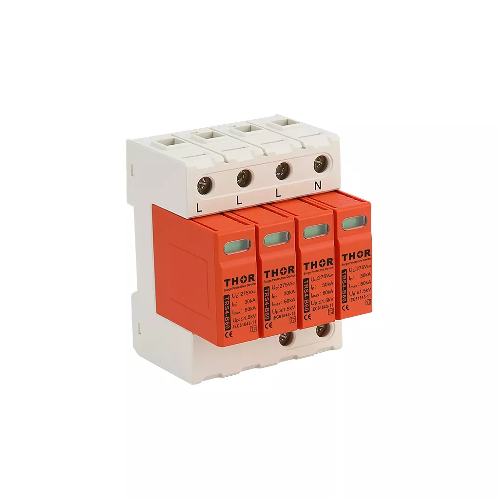
Figure 5: Thor TRS4-B60 Type 2 AC SPD. Pluggable module design, rated In 30kA / Imax 60kA, certified to IEC 61643-11/T2.
Selecting the right model comes down to two factors: Imax (match to the expected surge exposure of the installation) and Up (the lower the voltage protection level, the better the clamping for sensitive downstream equipment). All TRS4 models feature pluggable module design — the protection module can be replaced in the field without rewiring the base.
Type 3 SPD: Fine Protection at the Equipment Level
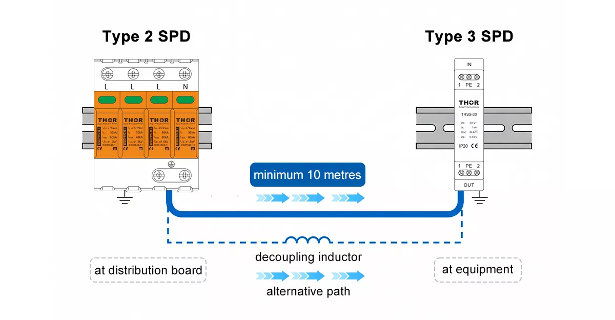
Figure 6: A minimum 10 metres of cable between Type 2 and Type 3 SPD is required for proper energy decoupling per IEC 61643-11. Where this distance is not achievable, a decoupling inductor can be used as an alternative.
Type 3 SPD is the final stage in a coordinated protection scheme. It installs close to or directly at the protected equipment and clamps the residual transient voltage that gets past the upstream Type 2 device.
Two conditions define when Type 3 is worth specifying: the equipment must be sensitive enough to warrant it (PLCs, medical devices, precision instruments, server hardware), and a Type 2 SPD must be installed upstream. A Type 3 device has a low discharge capacity and cannot survive direct exposure to distribution board surge levels.
IEC 61643-11 requires a minimum of 10 metres of cable between the Type 2 and Type 3 SPD. The distance creates the line impedance needed for the two devices to decouple properly. Where 10 metres is not physically possible, a decoupling inductor can be installed between the two devices to achieve the same effect.
Type 3 SPDs are tested with a combined waveform: 1.2/50µs voltage wave and 8/20µs current wave, reflecting the low-energy, fast transients they handle at the point of use.
Type 1+2 Combined SPD: When One Device Handles Both Roles
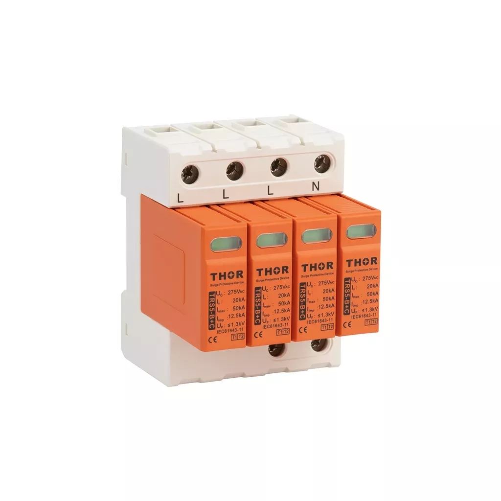
Figure 7: Thor TRS5-B+C Type 1+2 combined AC SPD. Handles both direct lightning current and switching transients in a single device, rated Iimp 12.5kA / Imax 50kA.
A Type 1+2 SPD is tested to both the 10/350µs and 8/20µs waveforms, handling direct lightning current and switching transients in a single device. The practical case for it is simple: where panel space is limited, or where a retrofit installation makes fitting separate Type 1 and Type 2 devices impractical, a combined unit simplifies the installation without compromising the protection grade.
The trade-off is Up. A combined device generally has a higher voltage protection level than a dedicated Type 2 SPD. For applications with very low impulse withstand equipment immediately downstream, a separate Type 2 with a lower Up may still be the better choice.
Thor’s TRS5-B+C covers this role well— Iimp 12.5kA, Imax 50kA, Up ≤1.3kV, certified to IEC 61643-11/T1+T2.
Choosing Between Type 1 and Type 2 SPD: Three Installation Scenarios
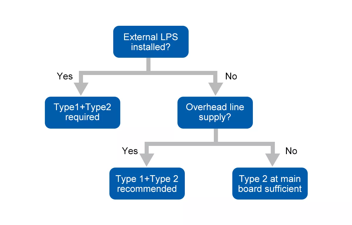
Figure 8: SPD type selection based on two key installation factors. Buildings with an external LPS or overhead line supply require Type 1 protection at the service entrance.
The correct SPD specification depends on two questions: how the building is supplied, and whether an external lightning protection system is present.
Scenario A: Building with an external LPS
Any building fitted with air terminals and down conductors per IEC 62305-3 — industrial facilities, telecommunications towers, high-rise buildings — requires a Type 1 SPD at the main distribution board. The practical solution is either a Type 1+2 combined device such as the TRS5-B+C, or a dedicated Type 1 (TRS-A series) with a coordinated Type 2 downstream.
Scenario B: Overhead line supply, no external LPS
Rural installations, suburban industrial sites, and any building supplied by overhead conductors fall into this category. An indirect lightning strike near the line injects surge current directly into the service entrance. For buildings supplied by overhead lines, a risk assessment per IEC 60364-5-53 will typically recommend Type 1 protection at the service entrance — even without a visible external LPS.
Scenario C: Underground cable supply, no external LPS
The most common situation in urban commercial and office buildings. Direct lightning current cannot enter through a buried cable supply, so Type 1 is not mandatory. A Type 2 SPD at the main distribution board is the correct baseline, with additional Type 2 devices at sub-distribution boards serving sensitive loads.
*In all three scenarios, Type 3 remains an option at the equipment level — required only where downstream electronics have impulse withstand voltages too low for Type 2 protection alone to cover.
Wiring Rules: Cable Sizing and Lead Length
Specifying the right SPD type is one thing — wiring it correctly is another. An incorrectly wired SPD can perform significantly worse than its datasheet suggests — sometimes offering almost no protection at all.
Lead length: keep it under 0.5 metres
The total length of conductors connecting the SPD to the circuit — L line plus PE line combined — must not exceed 0.5 metres. Every extra centimetre of lead wire adds inductance, which generates an additional voltage drop during a surge event. The result is that the actual let-through voltage at the protected equipment is higher than the SPD’s rated Up. Short leads are not a recommendation; they are a functional requirement.
Conductor cross-section
| SPD Type | L / N conductors | PE conductor |
| Type 1 | ≥6mm² | ≥16mm² |
| Type 2 | ≥2.5mm² | ≥6mm² |
Type 1 requires heavier conductors because it handles the sustained high-energy 10/350µs waveform — the thermal and mechanical stress on conductors during a direct lightning event is substantially greater than anything a Type 2 installation will see. For three-phase systems, conductor sizing also depends on your chosen 4+0 and 3+1 SPD configurations.
Frequently Asked Questions
Are Class I, Class II and Class III SPDs the same as Type 1, Type 2 and Type 3?
Yes. Class I, Class II and Class III are the older IEC/EN terminology for the same classification. Current editions of IEC 61643-11 use Type 1, Type 2 and Type 3. The devices, test requirements and performance criteria are identical — only the labelling convention changed between standard editions. If you encounter a datasheet referencing Class I or Class II, it refers to the same device category as Type 1 and Type 2 respectively.
Can a Type 2 SPD replace a Type 1?
No. A Type 2 SPD is tested to the 8/20µs waveform only. When exposed to a direct lightning current event — a 10/350µs impulse carrying 10 to 20 times more energy — it will fail immediately and catastrophically. Type 1 and Type 2 are not interchangeable at the service entrance of a building with an external LPS or overhead line supply.
Do I need a Type 3 SPD if I already have Type 1 and Type 2?
Not always. Type 3 is only necessary where downstream equipment has a low impulse withstand voltage that Type 2 protection alone cannot adequately cover — PLCs, medical devices, precision instruments and similar. For standard industrial and commercial equipment, a correctly specified Type 1 and Type 2 cascade is sufficient.
What is the minimum distance between Type 1 and Type 2 SPD?
IEC 61643-11 requires a minimum of 10 metres of cable between Type 1 and Type 2 SPDs to allow proper energy decoupling. If the physical installation cannot achieve this separation, a decoupling inductor must be installed between the two devices.
Need help specifying the right SPD for your project?
Thor Electric supplies IEC and TUV certified Type 1, Type 2, Type 3 and Type 1+2 AC surge protective devices to projects across 25+ countries. If you have a specification to match or a project to discuss, our technical team is ready to help.
Contact us to request samples, datasheets, or a project quotation.