An SPD sits in a high-impedance state during normal operation — it has no effect on the circuit. When a transient overvoltage causes the voltage across the device to exceed its maximum continuous operating voltage (Uc), the SPD switches to a low-impedance state in under 25 nanoseconds, creating a low-resistance path to earth. Surge current takes this path instead of travelling through your equipment. Once the surge has passed, the device returns to standby automatically.
As shown in Figure 1, the contrast between these two states is what makes surge protection effective: in normal conditions the current flows straight to the load; during a surge event it is redirected to earth before it can reach sensitive equipment downstream.
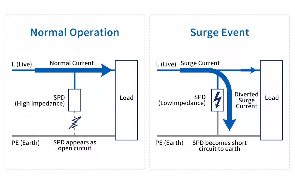
Figure 1: SPD working principle: normal operation (high impedance, current flows to load) vs surge event (low impedance, current diverts to PE)
The switching behaviour is driven by the SPD’s core protective component. In most AC and DC SPDs, this is a metal oxide varistor (MOV) — a voltage-dependent resistor whose resistance drops sharply when voltage exceeds a set threshold. Some Type 1 SPDs use a gas discharge tube (GDT) or spark gap instead, which handles higher energy surges characteristic of the 10/350µs lightning current waveform. In practice, many modern SPDs combine both technologies to balance response speed with energy-handling capacity.
Two parameters define what you see at the output during a surge event: the voltage protection level (Up) is the maximum residual voltage measured at the SPD terminals during testing, and it tells you how much voltage your downstream equipment will actually see when the device is clamping. Lower Up means better protection for sensitive loads.
The Three IEC-Defined SPD Types
IEC 61643-11 defines three SPD types based on their position in the electrical installation and the surge current waveform they are tested against. Each type handles a different level of surge energy, and in most installations they work as a coordinated cascade rather than standalone devices.
| Type 1 | Type 2 | Type 3 | |
| Test waveform | 10/350µs | 8/20µs | 1.2/50µs + 8/20µs |
| Key parameter | Iimp | In / Imax | Isc / Uoc |
| Installation point | Main service entrance / main panel | Sub-distribution board | Point of use, ≤10m from equipment |
| Primary threat | Direct lightning strikes, back-surge from LPS | Induced lightning, switching surges | Residual surges reaching sensitive equipment |
| Typical Up | ≤2.5kV | ≤1.5kV | ≤1.0kV |
Figure 2 illustrates where each type sits within a typical low-voltage installation, from the service entrance down to individual equipment.
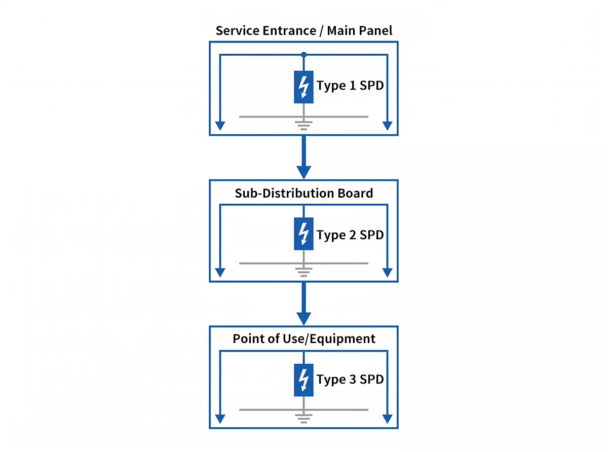
Figure 2: IEC-defined SPD types installation positions: Type 1 at main panel, Type 2 at sub-distribution board, Type 3 at point of use
A Type 1 SPD is required when a building has a lightning protection system (LPS) — the 10/350µs waveform it is tested against reflects the high-energy, long-duration current that flows when lightning discharges through an LPS earth conductor back into the installation. Without a Type 1 at the service entrance, that back-surge travels directly into the distribution network.
Type 2 is the most widely installed type. It handles the residual energy that passes through a Type 1, as well as internally generated switching surges from inductive loads such as motors, HVAC compressors, and transformers. In buildings without an LPS, a Type 2 at the main panel is the minimum recommended protection level under IEC 60364-5-53, as confirmed by the NEMA Surge Protection Institute.
Type 3 has a much lower discharge capacity and must always be installed as a supplement to Type 2, never as a standalone solution. Its value is in providing a low Up right at the terminals of sensitive equipment — PLCs, medical devices, precision instruments — where even the residual voltage passed by a Type 2 may cause problems.
What Is the Difference Between an SPD and an RCD?
An SPD and a residual current device (RCD) protect against completely different electrical hazards and are not interchangeable. An RCD detects earth leakage current caused by insulation faults or direct contact with live conductors, and disconnects the circuit within milliseconds to prevent electric shock. An SPD limits transient overvoltages — voltage spikes lasting microseconds — by diverting surge current to earth. One protects people from shock; the other protects equipment from surges. Both are required in a compliant low-voltage installation, and neither substitutes for the other.
Key SPD Parameters Explained
Understanding the meaning of each parameter in electrical SPD datasheets is essential for correct selection. These five values are defined in IEC 61643-11 and appear on every SPD datasheet.
Uc — Maximum Continuous Operating Voltage
The highest voltage an SPD can withstand continuously without activating. Uc must always exceed the maximum operating voltage of the system — if it does not, the SPD will conduct continuously, overheat, and fail. For a standard 230V AC system, a Uc of 275V is the typical minimum selection.
Up — Voltage Protection Level
The maximum residual voltage measured at the SPD terminals during a standardised surge test. This is the voltage your downstream equipment will see during a clamping event — lower is better. Up is a test value; connection lead length adds additional inductance that increases the effective let-through voltage at the equipment terminals, which is why IEC 61643-12 recommends keeping SPD connection leads as short as possible.
In — Nominal Discharge Current
The peak surge current (8/20µs waveform) an SPD can discharge repeatedly — at least 15 times under IEC test conditions — without degradation. In is the benchmark for Type 2 SPD endurance and the value most commonly cited in project specifications.
Imax — Maximum Discharge Current
The maximum single-event surge current (8/20µs) the SPD can handle without being destroyed. Imax is always higher than In and represents the device’s absolute ceiling under fault conditions. When comparing two Type 2 SPDs with the same In, the one with higher Imax carries a greater safety margin against abnormal surge events.
Iimp — Impulse Current
The peak current of a 10/350µs waveform that a Type 1 SPD can discharge at least once without failure. Because the 10/350µs waveform carries roughly 50 times more energy than an 8/20µs wave at the same peak current, Iimp values are not comparable to In or Imax — a Type 1 SPD rated at 12.5kA Iimp is handling significantly more energy than a Type 2 rated at 40kA Imax.
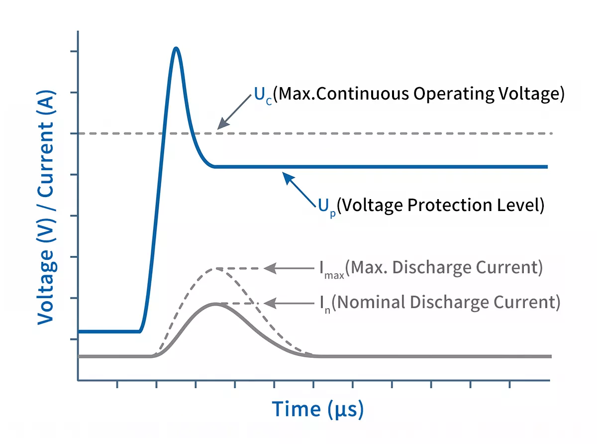
Figure 3: SPD key parameters diagram: Uc activation threshold, Up clamped output voltage, In/Imax/Iimp discharge current ratings on a surge waveform
Where Are SPDs Installed in an Electrical System?
SPD placement follows the structure of the electrical installation itself — each level of the distribution network has a corresponding SPD type, and protection is most effective when all three levels are covered.
At the service entrance or main distribution board, a Type 1 or Type 1+2 SPD handles the highest surge energies before they can propagate into the rest of the installation. This position is mandatory when the building has a lightning protection system, and strongly recommended in areas with high lightning exposure or critical loads.
At the sub-distribution board, a Type 2 SPD provides the second line of defence, absorbing residual surge energy that passes through the first stage and catching internally generated switching surges from motors, compressors, and other inductive loads on the same network. In buildings without an LPS, this is typically the primary protection point.
At the point of use — within 10 metres of sensitive equipment — a Type 3 SPD delivers the lowest Up values, ensuring that the small residual voltage passed by upstream devices does not affect PLCs, instrumentation, or other sensitive electronics. Type 3 must always be installed downstream of a Type 2; it cannot function as a standalone solution.
Beyond AC power lines, SPDs are equally necessary on DC and PV systems — surge current enters PV installations through array cabling and can destroy inverters and charge controllers. For DC-side protection requirements, the selection criteria differ significantly from AC systems — see solar panel surge protection.
Ethernet cables, PoE circuits, and coaxial feeds all act as surge entry paths, particularly in outdoor or long-run installations. Ethernet and PoE surge protection covers signal-line selection criteria in detail.
In many jurisdictions, SPD installation is no longer optional. Under BS 7671 in the UK, SPDs are the default requirement for most new installations unless a formal risk assessment justifies omission. In the US, the NEC has progressively expanded mandatory SPD coverage to include dwelling-unit services, industrial control panels, and critical occupancies. The global trend for 2025–2026 is toward broader mandatory adoption, not relaxation — if in doubt, the safe assumption is that an SPD is required.
Thor Electric SPD Recommendations
The following recommendations cover AC power line protection — the most common starting point for any surge protection strategy. Thor Electric also manufactures DC and PV SPDs, signal line SPDs, and LED-specific SPDs for applications beyond the AC distribution network. For those systems, see the relevant guides linked throughout this article or contact our team directly.
The three IEC-defined types map directly to Thor Electric’s AC SPD range. The right choice depends on your installation’s position in the distribution network and the level of lightning exposure at the site.
Type 1 — TRS-A Series
For service entrances in buildings with a lightning protection system, the TRS-A series handles direct lightning back-surge with Iimp ratings from 15kA up to 50kA (10/350µs). The TRS-A25, with Iimp 25kA and Up ≤2.2kV, covers the majority of commercial and industrial LPS installations. Where extremely high lightning exposure or large LPS earthing networks are involved, the TRS-A50 at Iimp 50kA provides additional margin.
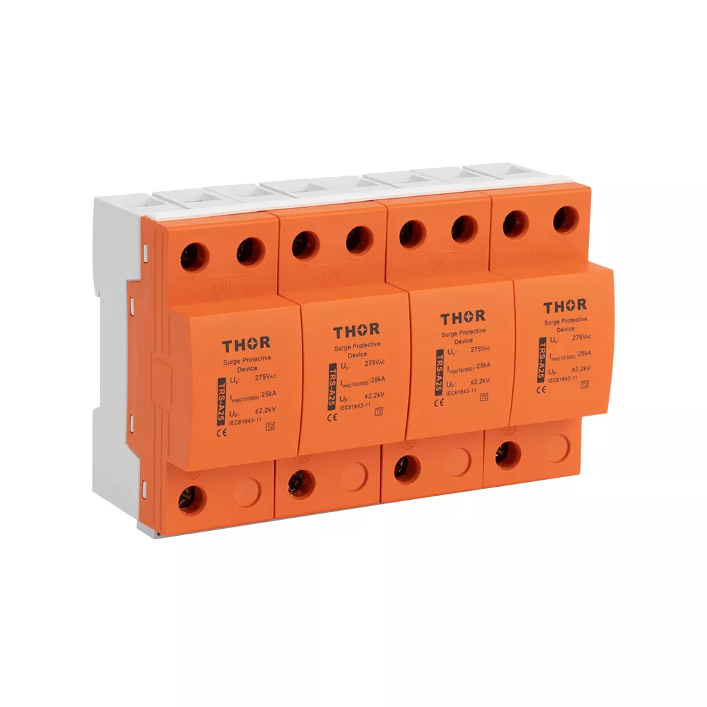
Figure 4: Thor TRS-A25 Type 1 AC Surge Protective Device
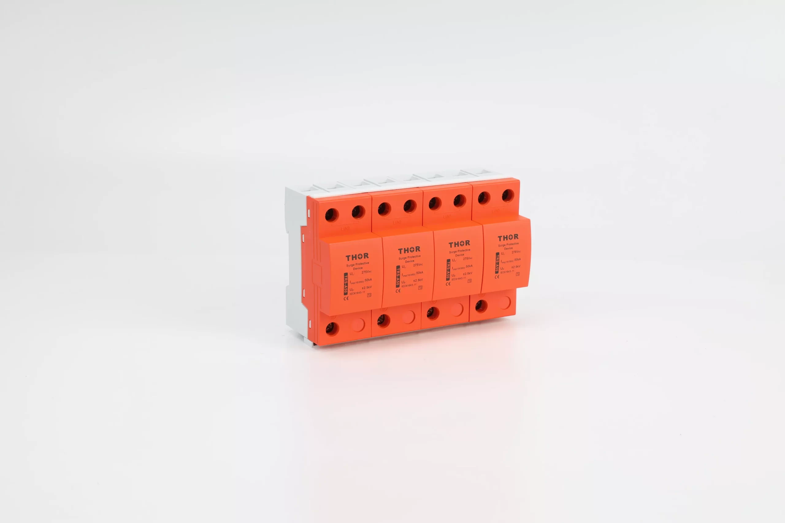
Figure 5: Thor TRS-A50 Type 1 AC Surge Protective Device
Type 1+2 — TRS5-B+C
Where a single device needs to cover both direct lightning and switching surge protection — typically at the main distribution board of a facility without a dedicated Type 1 upstream — the TRS5-B+C combines Iimp 12.5kA (10/350µs) with Imax 50kA (8/20µs) and Up ≤1.3kV in a single pluggable module. This is the most practical choice for most commercial and light industrial installations.
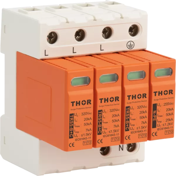
Figure 6: Thor TRS5-B+C Type 1+2 AC Surge Protective Device
Type 2 — TRS4-B60
At the sub-distribution board level, the TRS4-B60 delivers In 30kA and Imax 60kA (8/20µs) with Up ≤1.5kV. For three-phase installations, wiring configuration at this level directly affects protection coverage; see our guide to 4+0 vs 3+1 configuration in SPDs for wiring configuration options.
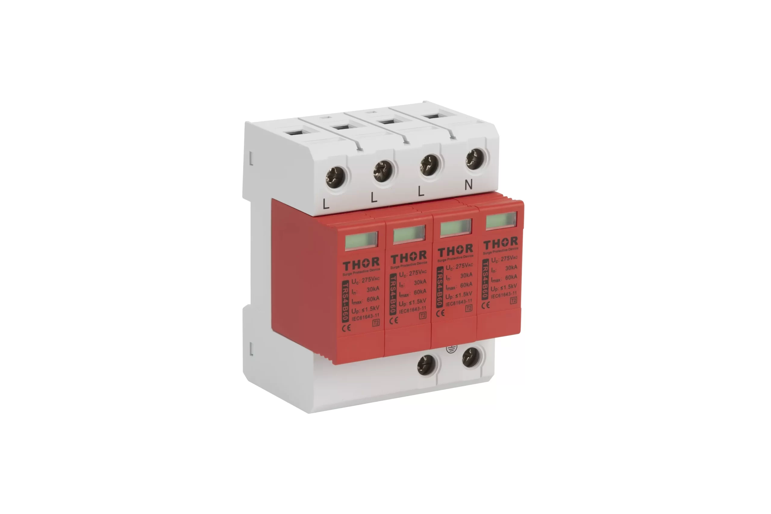
Figure 7: Thor TRS4-B60 Type 2 AC Surge Protective Device
All Thor Electric SPDs are certified to IEC, TUV, CE, RoHS, CB and ISO standards. Pluggable module design allows field replacement without rewiring — when the status indicator shows red, the module is swapped in seconds, downtime is eliminated.
Specifying the Right SPD for Your Installation
The right SPD selection starts with three questions: where in the distribution network is the device going, what is the lightning exposure at the site, and what equipment downstream needs to be protected. Type, Uc, Up, and discharge current ratings all follow from those answers.
If you are specifying SPDs for a new installation or replacing existing devices, our team can assist with parameter selection, wiring configuration, and coordination between protection levels. We supply to electrical contractors, panel builders, and procurement teams across 25+ countries, with samples available on request.
Frequently Asked Questions (FAQs)
Q: What does SPD stand for in electrical systems?
SPD stands for Surge Protective Device — a component connected in parallel with an electrical installation to limit transient overvoltages and divert surge current safely to earth. It activates only when voltage exceeds its rated threshold, protecting equipment from lightning strikes, utility switching, and inductive load surges.
Q: What is the difference between an SPD and an RCD?
An SPD limits transient overvoltages by diverting surge current to earth — it protects equipment. An RCD detects earth leakage current and disconnects the circuit to prevent electric shock — it protects people. Both are required in a compliant low-voltage installation and neither substitutes for the other.
Q: What are the three types of SPD?
Type 1 is installed at the main service entrance, rated for direct lightning surges (10/350µs waveform). Type 2 goes at the sub-distribution board, handling residual and switching surges (8/20µs). Type 3 is installed at the point of use, within 10 metres of sensitive equipment, and must always be downstream of a Type 2.
Contact our team at spds.global/contact-us/ to discuss your project requirements.