Pick up any Type 1 SPD datasheet and you will find a gas discharge tube listed as the first protection stage. The component is simple: a sealed enclosure, two or three metal electrodes, and an inert gas fill. Below its DC sparkover voltage it does nothing — essentially open circuit, invisible to the rest of the circuit. Push the voltage above that threshold and the gas ionises in under 100 ns, opening a low-resistance path to earth. When the surge clears, the gas de-ionises and the device is ready for the next event.
The reason GDTs sit at the front of Type 1 and Type 1+2 SPDs is energy. A direct lightning strike delivers current on a 10/350 µs waveform — roughly 20 times the specific energy of the 8/20 µs waveform that metal oxide varistor (MOV) are rated against. The GDT takes the first hit; the MOV handles the residual clamping. For signal and RF lines the logic is different: capacitance is under 1 pF, so the device sits in-line without affecting the signal, conducting only when a surge exceeds the sparkover threshold.
What Is a Gas Discharge Tube?
A gas discharge tube (GDT) is a sealed ceramic or glass enclosure containing two or three metal electrodes separated by an inert gas fill. It acts as a voltage-dependent switch: below its sparkover voltage it is effectively open circuit; above it, the gas ionises and the GDT conducts surge current to earth in under 100 ns, protecting connected equipment from overvoltage damage.
The enclosure is ceramic or glass, hermetically sealed, with electrodes set a precise distance apart. That gap distance, combined with the gas type and fill pressure, determines the DC sparkover voltage (Vs). Below Vs the gas is an insulator. Exceed it and the gas ionises — the GDT conducts, surge current diverts to earth, and the protected equipment sees only the residual clamped voltage. The component is also called a gas arrester tube or spark gap arrester depending on the application context.
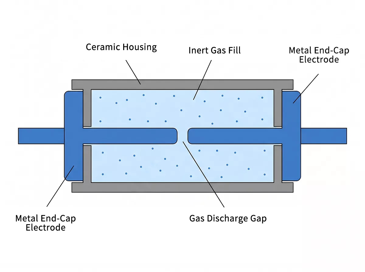
Figure 1: Cross-section diagram of a 2-electrode gas discharge tube showing ceramic body, electrodes and inert gas fill
The term GDT covers a range of components from small signal-line arresters (rated at a few hundred amperes) to high-energy power-line units rated at Iimp 25 kA or above. The circuit diagram symbol shows two parallel lines (electrodes) with a circle (the gas-filled enclosure) — a 3-electrode version adds a third electrode at 90° to the first two.
How Does a Gas Discharge Tube Work?
The working principle follows four distinct states during a surge event:
1. Standby (insulating state): The applied voltage is below Vs. The gas is un-ionised — essentially open circuit. Leakage current is typically below 1 µA. The GDT has no effect on the circuit.
2. Ionisation (sparkover): Vs is exceeded. The gas ionises in under 100 ns. The component switches from open circuit to conductor.
3. Arc conduction: The gas conducts. Voltage across the device drops to around 10–20 V and surge current flows to earth. Duration is microseconds for lightning impulses, up to a few milliseconds for switching surges.
4. Recovery: Current drops below the hold threshold, conduction stops, and the gas de-ionises. The GDT returns to its insulating state. Recovery takes 1–10 ms depending on gas mixture and electrode geometry.
The key parameter governing sparkover is the DC sparkover voltage (Vs), measured per IEC 61643-311. For power-line GDTs used in AC SPDs, Vs typically ranges from 230 V to 600 V DC. For signal-line variants (RS-485, coaxial), Vs is set lower — often 90 V to 230 V — to protect sensitive electronics. Note that the impulse sparkover voltage is slightly higher than the DC value, which is accounted for in SPD design.
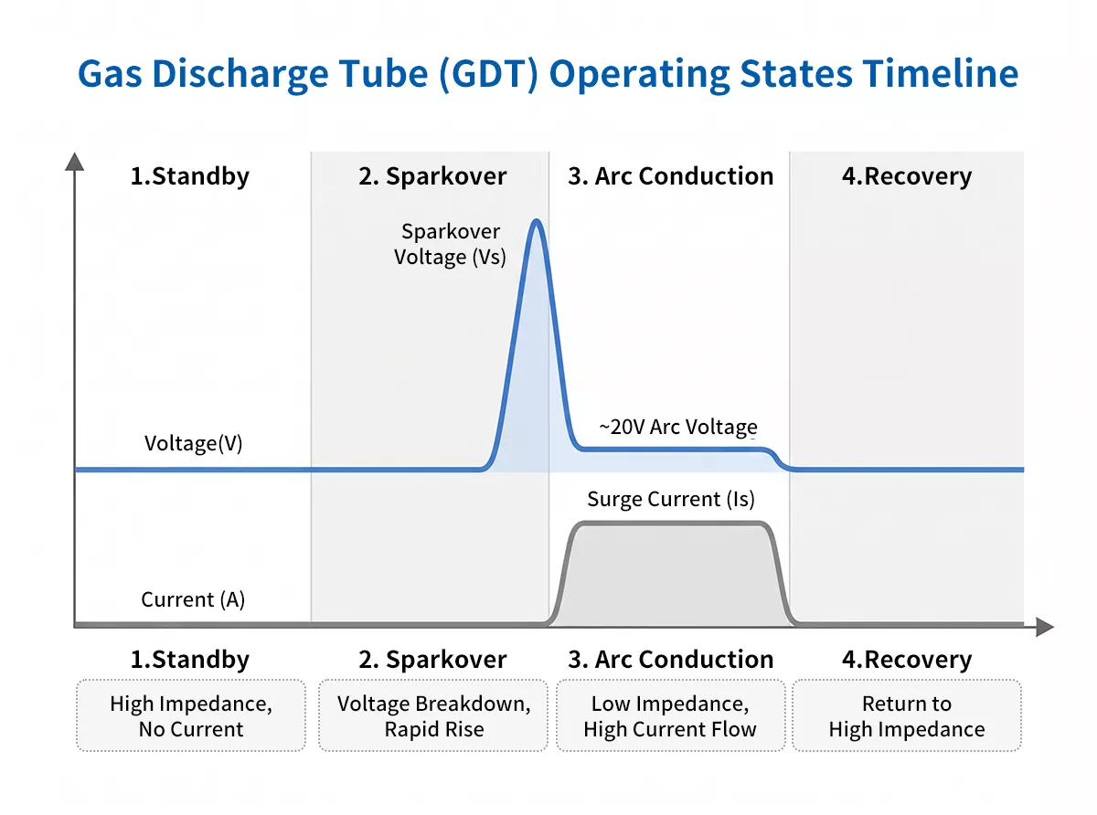
Figure 2: Gas discharge tube operating states: standby, sparkover, arc conduction and recovery — voltage/current waveform diagram
Which Gas Is Used in a Gas Discharge Tube?
The gas fill determines the sparkover voltage, response characteristics, and service life. Three inert gases are used in commercial arresters:
| Gas | Typical Vs range | Characteristics |
| Argon (Ar) | 70–600 V DC | Most common fill gas. Good ionisation characteristics, stable sparkover voltage, wide operating temperature range. |
| Neon (Ne) | 100–800 V DC | Higher sparkover voltage than argon. Used where a higher Vs threshold is required. Slower recovery than argon. |
| Argon/Neon mixture | Tunable by ratio | Blending the two gases allows manufacturers to set precise Vs values and optimise the trade-off between response speed and recovery time. |
For most industrial SPD applications, standard argon-filled GDTs are specified.
2-Electrode vs 3-Electrode GDT: How to Choose
In practice this choice is made by the SPD manufacturer, not the installer. But knowing the difference matters when comparing datasheets or specifying a replacement module.
● 2-electrode: Two electrodes face each other across a single gas gap. Connect it between one conductor and earth, or across two conductors. Low capacitance, high current capacity, straightforward to replace. THOR’s TRSW coaxial SPD series uses a replaceable 2-electrode unit as the primary protection element, connected between the inner conductor and the metal housing (earth).
● 3-electrode: A third electrode is added at 90° to the first two, creating two spark gaps in a single enclosure. It allows simultaneous protection of two conductors to a common earth — useful for balanced signal lines (RS-485, telephone) where both conductors must be clamped symmetrically. The two gaps fire simultaneously, maintaining the differential voltage balance between the two signal conductors.
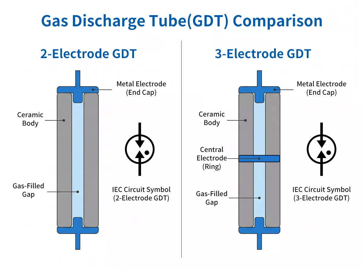
Figure 3: 2-electrode vs 3-electrode gas discharge tube structure and circuit symbol comparison
For three-phase power-line SPDs, three separate 2-electrode GDTs are used (one per phase), not a single 3-electrode unit. The 3-electrode configuration is specific to balanced signal-line applications.
Gas Discharge Tube vs MOV vs TVS Diode: Comparison
GDT, MOV, and TVS diode are not interchangeable — each serves a distinct role in the protection cascade, and each fails differently under stress.
| Parameter | GDT | MOV | TVS Diode |
| Operating principle | Gas ionisation (spark gap) | Zinc oxide varistor (non-linear resistance) | Avalanche breakdown (semiconductor) |
| Response time | < 100 ns (impulse); 1–10 µs (DC sparkover) | < 25 ns | < 1 ps |
| Capacitance | < 1 pF (2-electrode) | 100 pF – 10 nF | 10 pF – 10 nF |
| Energy capacity | Very high — Iimp up to 25 kA (10/350 µs) | Medium — Imax up to 60 kA (8/20 µs) | Low — typically < 600 W peak |
| Clamping voltage | Drops to 10–20 V after sparkover | Moderate — typically 1.0–1.5 kV for AC SPDs | Low — precise clamping close to Vbr |
| Typical application | First-stage (Type 1) power and signal SPDs; coaxial/RF protection | Second-stage (Type 2) power SPDs; general-purpose surge suppression | Fine protection (Type 3); sensitive electronics, PCB-level |
| Limitation | Follow current risk on AC lines; slower sparkover than MOV/TVS | Degrades with repeated surges; high capacitance affects signal lines | Low energy capacity; not suitable for direct lightning exposure |
The near-zero capacitance (< 1 pF for a 2-electrode unit) makes the GDT the only viable first-stage protection element for high-frequency signal lines. An MOV with 1 nF capacitance would attenuate a 500 MHz RF signal by several dB — unacceptable for antenna or coaxial applications. The GDT passes the signal without measurable insertion loss, then conducts only when a surge exceeds Vs.
The limitation of the GDT on AC power lines is follow current: after the surge clears, the AC mains voltage can keep the device conducting if it stays above the hold threshold. Well-designed SPDs address this with a series MOV or a current-limiting element that cuts off conduction at the next AC zero crossing.
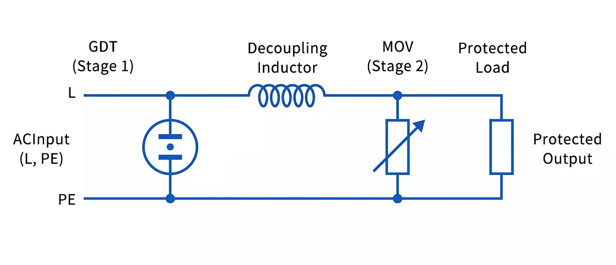
Figure 4: Coordinated protection circuit showing GDT (first stage) and MOV (second stage) in series with decoupling impedance
Gas Discharge Tube in SPD: Role and Applications
In a Type 1 or Type 1+2 SPD, the GDT handles the first and most energetic stage of protection. When a direct or nearby lightning strike injects a 10/350 µs impulse current into the installation, it conducts the bulk of that energy to earth before it reaches the MOV stage. Without it, the MOV would absorb the full 10/350 µs energy — a waveform with roughly 20 times the specific energy of the 8/20 µs test waveform — and fail.
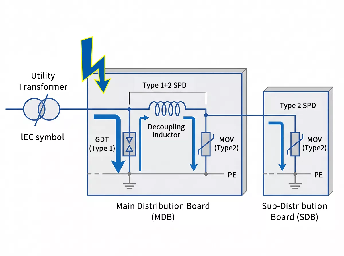
Figure 5: GDT placement in a Type 1+2 SPD installation — main distribution board showing GDT first stage and MOV second stage positions
Without a decoupling impedance between the two protection stages, the MOV responds first — it is faster — and absorbs the full surge energy before the GDT conducts. The decoupling element (an inductor or resistor) slows the voltage rise seen by the MOV, giving the GDT time to conduct. Without it, the MOV takes the full hit on the first high-energy event.
For signal and RF lines, the GDT operates as a standalone protection element rather than in a coordinated cascade. The low capacitance preserves signal integrity, while the high current capacity (10 kA for coaxial SPDs) handles direct lightning coupling into antenna or feeder cables.
GDT in Coaxial and RF Signal SPDs
Thor Electric’s TRSW series coaxial SPDs use a replaceable integrated GDT as the protection element. The metal housing provides the earth reference, and the GDT connects between the inner conductor and the housing. Key specifications: 10 kA current capacity, frequency range DC–2.5 GHz (N, TNC, SMA connectors) or DC–2 GHz (BNC), insertion loss ≤0.3 dB, VSWR < 1.2, impedance 50 Ω.
The replaceable design means the SPD housing and connectors remain in service after a surge event — only the GDT module is replaced. This reduces maintenance cost on installations with multiple antenna feeds, such as CCTV systems, cellular base stations, and industrial wireless networks.
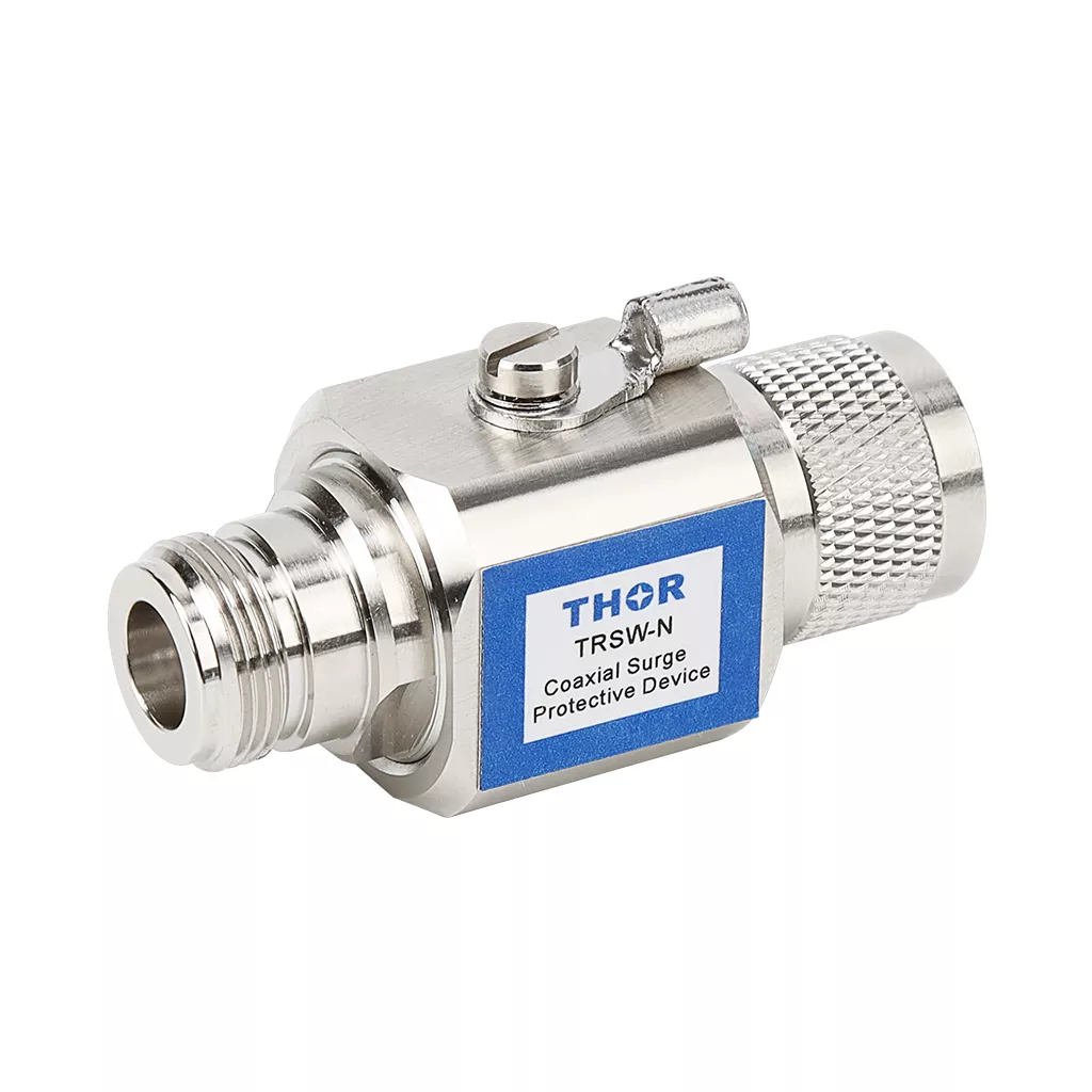
Figure 6: Thor TRSW coaxial SPD with replaceable GDT module, shown with N-type connector
For gas discharge tube lightning protection on RS-485 and control signal lines, Thor’s TRSS-485 series uses GDT-based protection at the signal interface, with available protection voltages of 5 V, 12 V, 24 V, and 100 V to match the signal level of the protected circuit.
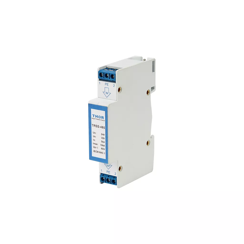
Figure 7: Thor TRSS-485 RS-485 signal surge protector with GDT protection, DIN rail mounted
Key Parameters When Selecting a Gas Discharge Tube
When specifying a GDT for an SPD design or replacement, four parameters determine suitability:
| Parameter | What it means | Typical values |
| DC sparkover voltage (Vs) | The voltage at which the GDT conducts. Must be above the circuit’s peak operating voltage to avoid false triggering, but below the equipment’s damage threshold. | 350–600 V DC for 230 V AC circuits 90–150 V for 48 V signal lines |
| Impulse current rating (Iimp / Imax) | How much surge current the device can handle. Iimp (10/350 µs) is the Type 1 rating for direct lightning. Imax (8/20 µs) is the Type 2 rating. Undersizing this is the most common cause of SPD failure. | Iimp: 12.5–25 kA (Type 1) Imax: up to 60 kA (Type 2) |
| Capacitance | How much the GDT loads the signal line. Critical for RF and high-frequency signal applications — a high-capacitance component would degrade the signal. | < 1 pF for 2-electrode types Negligible up to several GHz |
| Service life (impulse endurance) | GDTs degrade with each surge event. Manufacturers specify how many impulses the device can handle before replacement. For high-lightning-density sites, choose SPDs with replaceable GDT modules. | Varies by model Replaceable module designs (e.g. TRSW series) simplify maintenance |
Signal-line SPDs with GDTs are tested to IEC 61643-21, which covers sparkover voltage measurement, impulse current withstand, and insertion loss verification. For power-line SPDs, IEC 61643-11 applies.
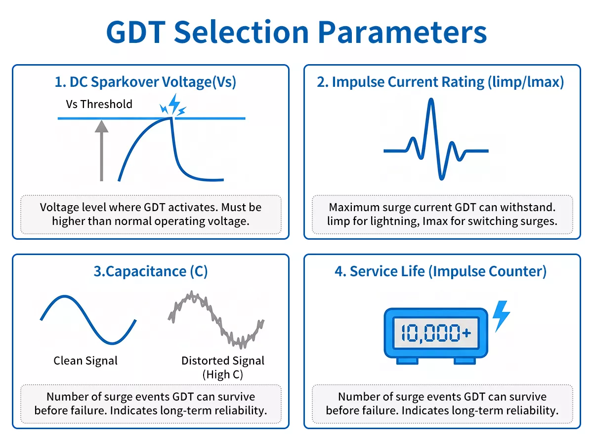
Figure 8: Gas discharge tube key selection parameters overview: sparkover voltage, impulse current, capacitance and service life
Get the Right SPD for Your Application
For project-specific SPD specifications incorporating gas discharge tube protection — whether for power, signal, or coaxial applications — contact the Thor Electric team directly.