What Is a TN-C-S Earthing System?
A TN-C-S earthing system combines a shared PEN (Protective Earth and Neutral) conductor from the distribution network to the service head, where it splits into separate N and PE conductors at the consumer unit. In the UK, this arrangement is known as PME (Protective Multiple Earthing) and is the standard supply method used by Distribution Network Operators (DNOs) for the majority of domestic and commercial premises.
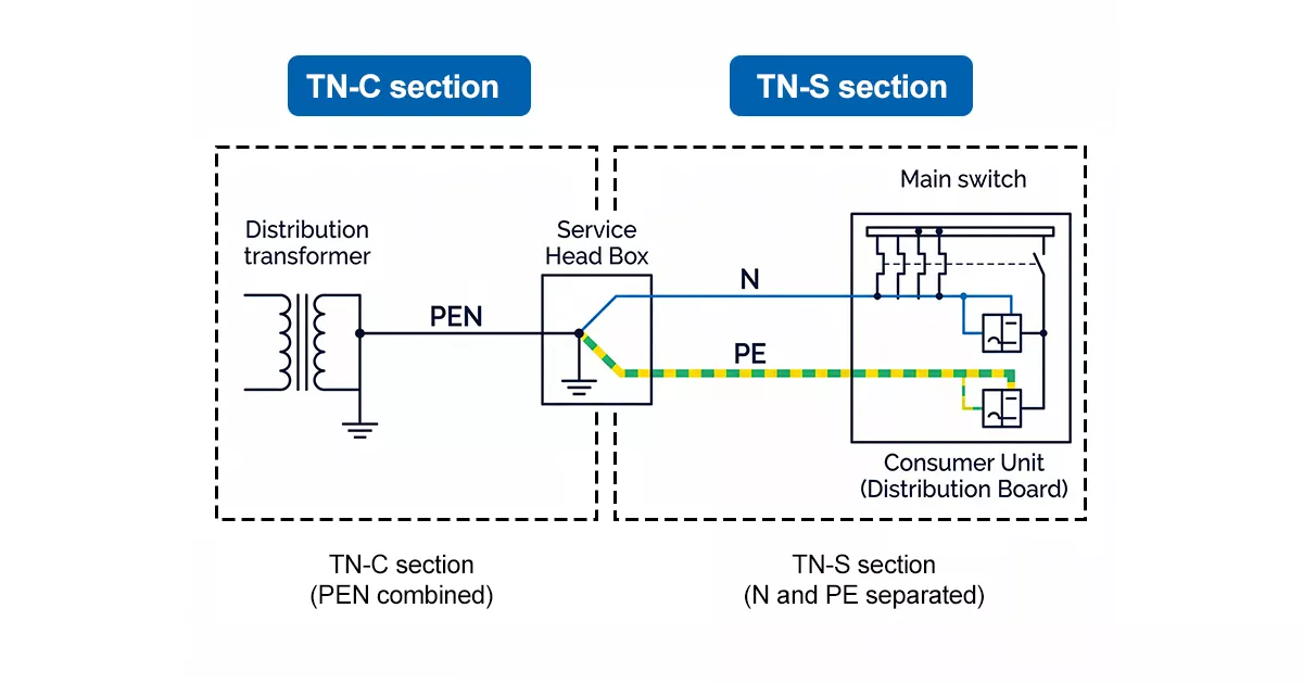
Figure 1 — TN-C-S system single-line diagram showing PEN conductor from transformer, split point at service head, separate N and PE to installationer unit
The IEC 60364 standard defines 3 types of earthing systems — TN, TT, and IT — with TN further subdivided into TN-S, TN-C, and TN-C-S. In a TN-C-S installation, the ‘C’ portion (combined PEN) runs from the transformer to the point of supply, and the ‘S’ portion (separated N and PE) covers the internal installation from that point onward.
The PEN conductor in the TN-C-S section is earthed at multiple points along the distribution network — hence Protective Multiple Earthing. The multi-point earthing keeps the earth fault loop impedance low, which is a key advantage for automatic disconnection of supply (ADS) under BS 7671.
TN-C-S vs TN-S vs TT: Key Differences
Understanding how the TN-C-S system compares to TN-S and TT is useful when specifying protection equipment. The table below summarises the key differences relevant to electrical engineers and SPD selection.
| TN-S | TN-C-S (PME) | TT | |
| Earth return path | Separate PE conductor throughout | PEN to service head, then separate N and PE | Local earth electrode |
| PE arrangement | Dedicated PE from transformer | PEN splits at consumer unit | Independent earth rod at premises |
| Typical use | Older UK installations, sensitive equipment sites | Standard UK DNO supply (majority of premises) | Rural areas, overhead line supplies |
| SPD implication | 4+0 or 3+1 both viable | 3+1 configuration required — not 4+0 | Separate earth electrode; SPD Uc must account for higher Ze |
| Broken neutral risk | Low — PE is independent | High — broken PEN raises metalwork to line voltage | N/A — no shared PEN |
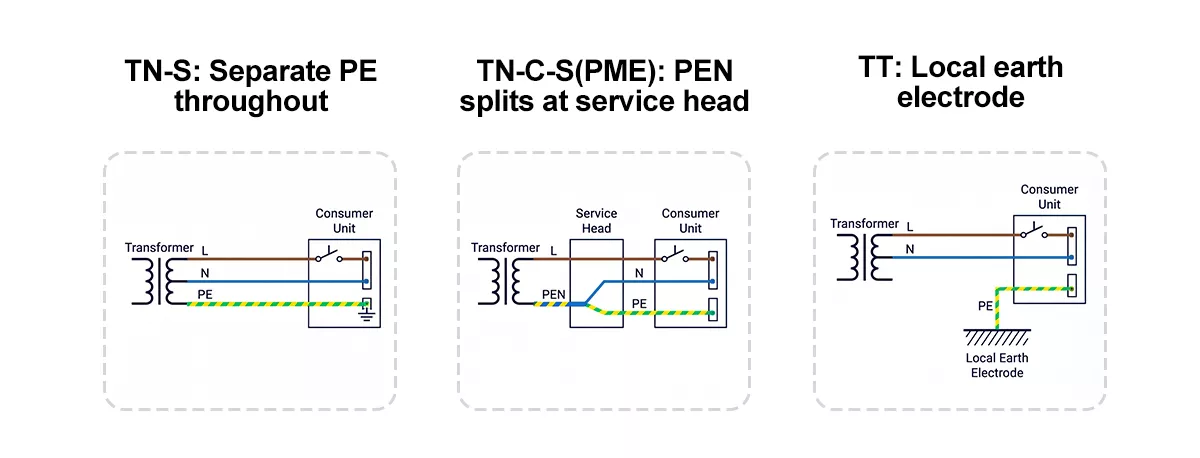
Figure 2 — Side-by-side comparison of TN-S, TN-C-S and TT earthing arrangements showing earth return
The TN-C-S earthing system is the most common supply arrangement in the UK because it eliminates the need for a separate earth electrode at each premises. TN-S is preferred for sensitive installations — data centres, hospitals, and sites with high harmonic loads — where a clean, independent PE is required. The TT earthing system is common in rural areas served by overhead lines, where the DNO cannot guarantee a low-impedance earth return path.
One question that arises in mixed-supply areas: can you have TNCS and TT on the same site? In practice, no — the earthing system is determined by the DNO supply. A premises receiving a PME supply cannot simply switch to TT without installing an independent earth electrode and disconnecting from the PME terminal, which requires DNO agreement.
TN-C-S Wiring Diagram and Circuit Structure
In a TN-C-S earthing system wiring diagram, the PEN conductor runs from the distribution transformer to the service head (cut-out) at the premises. At the service head or meter tails, the PEN splits: the neutral (N) continues to the neutral bar in the consumer unit, and the protective earth (PE) connects to the earth bar, which is bonded to the incoming metallic services and the main protective bonding conductors.
From the consumer unit onward, N and PE are kept separate throughout the installation. This is the defining characteristic of the ‘S’ (separated) portion of TN-C-S. The split point is typically at the DNO service head or at the meter position, depending on the network configuration.
One rule applies without exception: the PEN conductor must never be interrupted. Any break in the PEN — whether from corrosion, mechanical damage, or a loose connection — removes the earth reference from the installation while the neutral remains live. This causes exposed metalwork to rise toward line voltage (230 V), creating a lethal shock hazard. IEC 60364-5-54 and most national electrical codes prohibit the use of a switch or fuse in the PEN conductor for this reason.
After the split point, the installation follows standard TN-S wiring practice. Ring finals, radial circuits, and sub-distribution boards all use separate N and PE conductors. The PME earth terminal at the consumer unit serves as the reference point for all protective bonding within the premises.
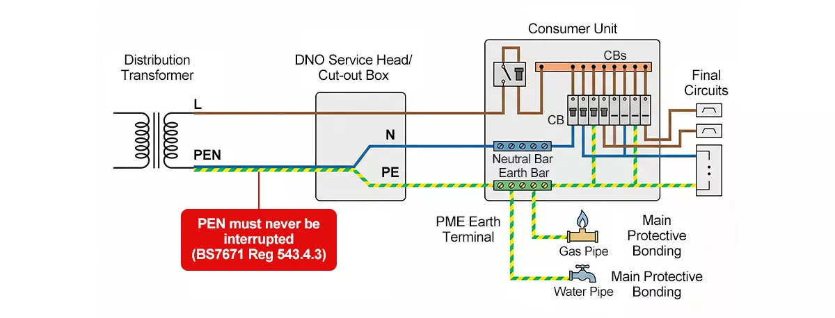
Figure 3 — TN-C-S wiring diagram showing PEN conductor from transformer to service head, split into separate N and PE at consumer unit
Advantages and Disadvantages of TN-C-S
The advantages of TN-C-S earthing systems are well established, making it a common choice for electrical distribution in residential and commercial installations:
● No separate earth electrode required at the premises — the DNO provides the earth reference via the PEN conductor, reducing installation cost and complexity.
● Low earth fault loop impedance (Ze typically 0.35Ω or below for urban supplies) — this enables fast automatic disconnection of supply under fault conditions, satisfying BS 7671 ADS requirements without the need for RCDs on every circuit.
● Consistent earth reference across the installation — the PME terminal provides a stable, low-impedance earth that supports reliable operation of protective devices.
● Lower installation cost compared to TN-S — no separate earth conductor is required in the distribution network from transformer to premises.
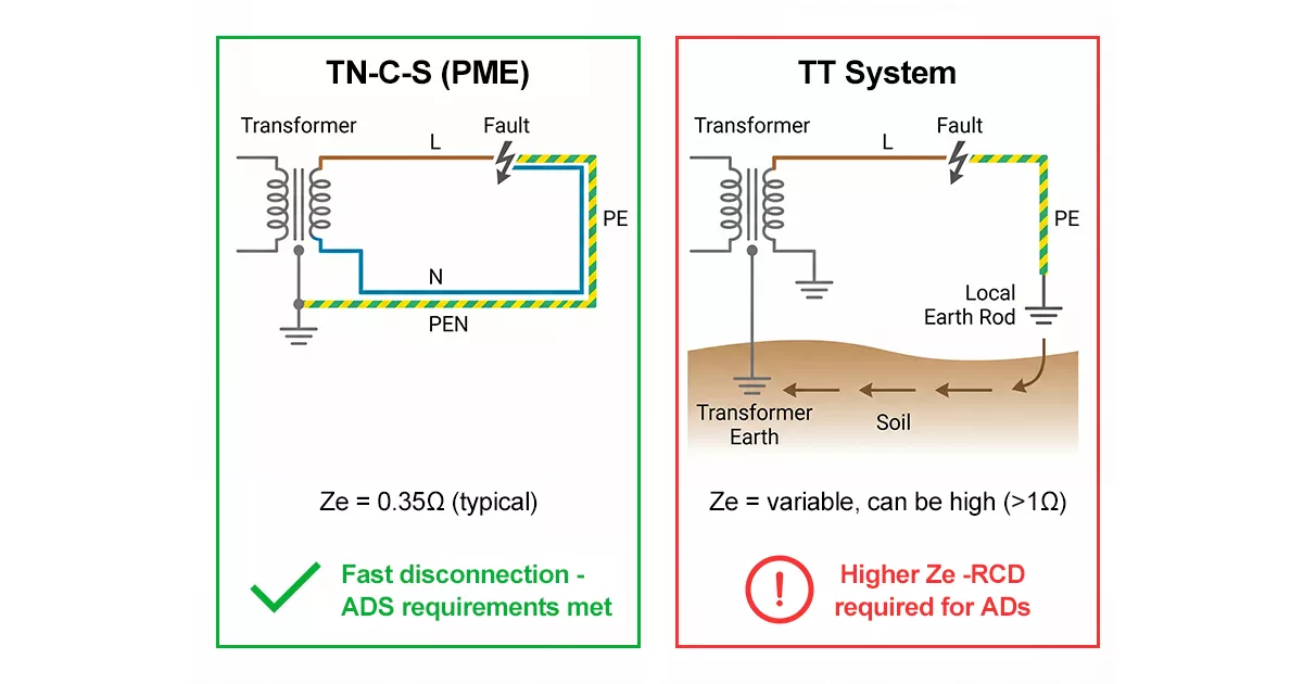
Figure 4 — TN-C-S low earth fault loop impedance compared to TT system requiring local earth electrode
The disadvantages of TN-C-S earthing system centre on the shared PEN conductor and the risks that arise if it is compromised:
● Broken PEN risk: if the PEN conductor breaks between the transformer and the service head, the installation loses its earth reference. Under load, the neutral point shifts, and exposed metalwork can rise to line voltage (up to 230 V). This is the most serious hazard associated with PME supplies.
Transient overvoltage (TOV) risk for SPDs: during a PEN conductor break, the phase-to-earth voltage at the installation can rise to 400 V (line-to-line voltage) for several seconds before protective devices operate. SPDs installed in 4+0 configuration face this voltage directly across the N-PE varistor, which can cause thermal runaway and SPD failure.
● Restricted use in certain locations: BS 7671 Regulation 8(4) and the ESQCR prohibit the use of the PME earth terminal as the sole means of earthing for swimming pools, caravan sites, marinas, and agricultural premises, due to the elevated risk of electric shock from broken PEN faults in these environments.
● Neutral current on PE conductors: because N and PE share the same conductor in the TN-C section, any imbalance in the distribution network can introduce small currents on the PE conductor within the installation. This is generally not a safety issue but can cause interference in sensitive electronic systems.
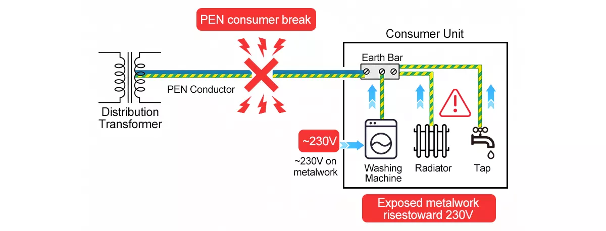
Figure 5 — Diagram showing broken PEN conductor causing voltage rise on exposed metalwork in TN-C-S installation
How TN-C-S Affects SPD Selection and Configuration
The earthing system type directly determines how an SPD must be wired. For a TN-C-S earthing system, the correct configuration is 3+1, not 4+0. This distinction matters for both safety and compliance with IEC 61643-11.
In a 4+0 configuration, all four varistors (L1-PE, L2-PE, L3-PE, N-PE) are connected in parallel across the supply. The N-PE varistor sits directly across the supply neutral. If the PEN conductor breaks upstream, the N-PE MOV faces the full line-to-line voltage (400 V) sustained for several seconds. The result is thermal runaway, SPD failure, and potential fire.
In a 3+1 configuration, the three line conductors (L1, L2, L3) are protected to neutral, and a separate SPD handles the N-PE path. Per IEC 61643-11, the SPD must survive 5 seconds at 1.47 x Uc to pass the TOV test. For a Uc of 275 V AC, this means withstanding approximately 404 V for 5 seconds.
For a detailed explanation of the wiring differences, see 4+0 vs 3+1 SPD configuration.
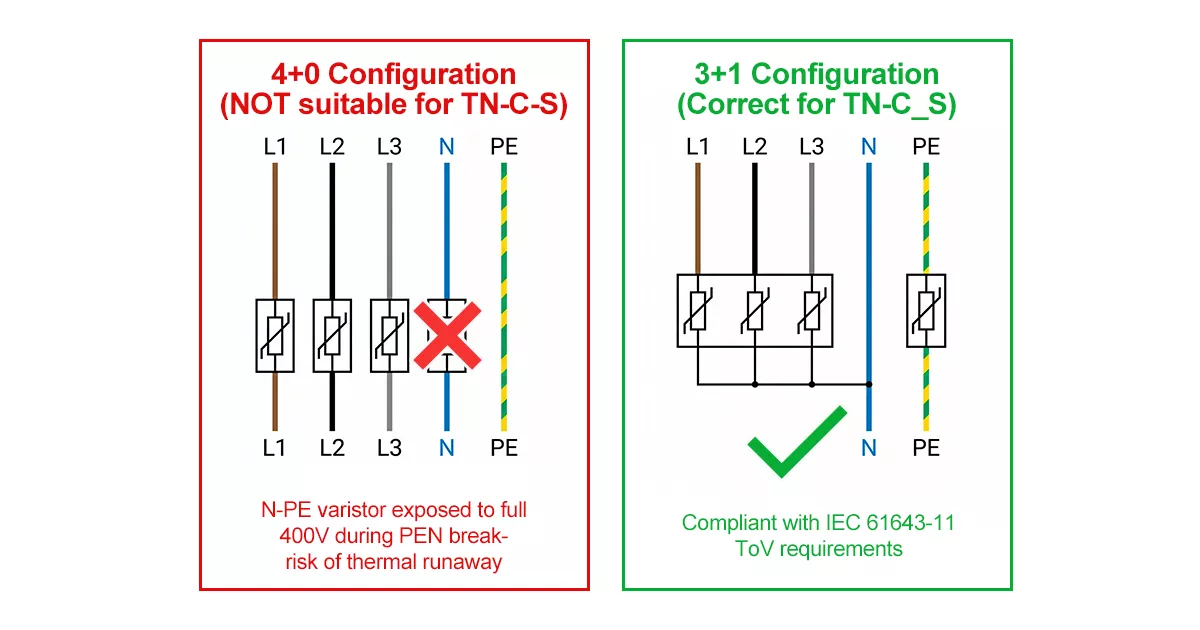
Figure 6 — 3+1 vs 4+0 SPD configuration wiring diagram for three-phase TN-C-S installation
For the main distribution board in a TN-C-S installation with a lightning protection system (LPS), Thor’s TRS5-B+C Type 1+2 SPD is appropriate: Iimp 12.5 kA, Up ≤1.3 kV, Uc 275 V AC, certified to IEC 61643-11 T1+T2. The 3P version protects L1/L2/L3 to neutral, with a separate 1P unit handling the N-PE path in the 3+1 arrangement.
For sub-distribution boards where Type 1 protection is not required, the TRS4-B60 Type 2 SPD provides In 30 kA, Imax 60 kA, Up ≤1.5 kV, Uc 275 V AC. Again, the 3+1 wiring principle applies: three poles for L1/L2/L3-N protection, plus a separate pole for N-PE.
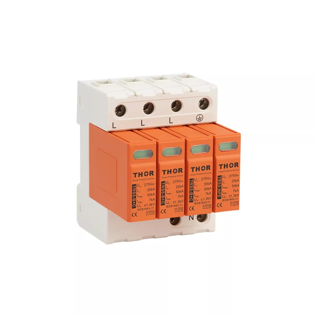
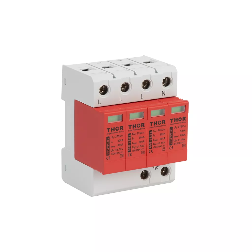
Figure 7 — Thor TRS5-B+C Type 1+2 SPD (left) and TRS4-B60 Type 2 SPD (right) for TN-C-S installations
SPD Pole Selection for TN-C-S Systems
Pole selection depends on whether the installation is single-phase or three-phase:
Single-phase TN-C-S (UK domestic 230 V): A 2-pole SPD covering L and N is the standard choice. Thor’s TRS2-C40 1P+N Type 2 SPD (In 20 kA, Imax 40 kA, Uc 255/275 V AC) is designed for this application. In single-phase PME installations, the N-PE connection is made at the consumer unit earth bar, so the SPD protects the L-N path while the PME earth provides the reference.
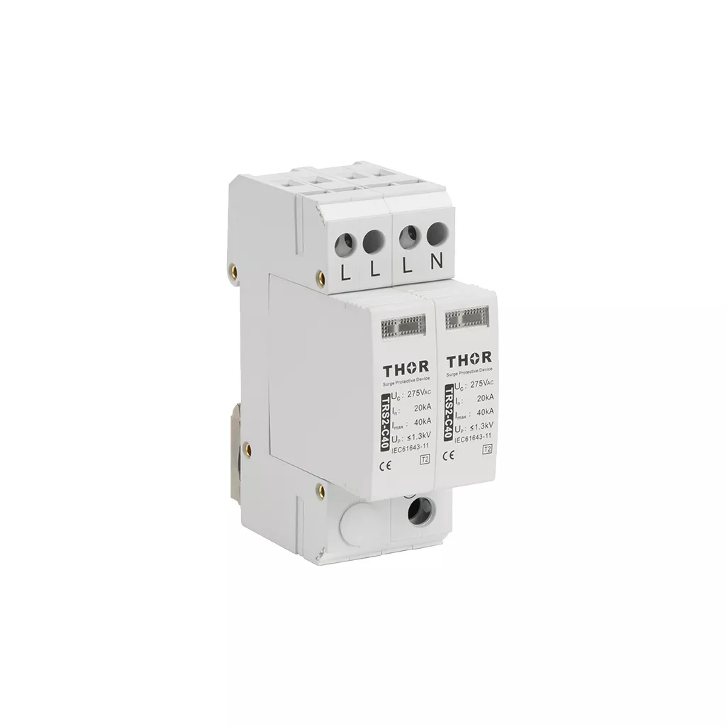
Figure 8 — Thor TRS2-C40 1P+N SPD installed in single-phase TN-C-S consumer unit
Three-phase TN-C-S (commercial/industrial 400 V): The 3+1 arrangement requires a 3-pole SPD for L1/L2/L3-N protection, plus a separate 1-pole SPD for the N-PE path. These are installed as two discrete units, not a single 4-pole SPD in 4+0 mode. The combined result is four-pole protection in the correct 3+1 configuration.
Why not use a single 4-pole SPD in 4+0 mode for three-phase TN-C-S? Because the N-PE varistor in a 4+0 unit is not rated for the sustained TOV that occurs during a PEN conductor break. A dedicated N-PE SPD with appropriate TOV withstand is the only compliant solution for PME earthing system installations.
For project-specific SPD specifications suitable for TN-C-S and PME installations, contact the Thor Electric team directly