
The air termination is the part of a lightning protection system that takes the strike: rods, roof conductors, catenary wires, or roof metal thick enough to do the job. The down conductor carries that current from the roof to the earth termination. For most buildings designed to IEC 62305-3, both are 50 mm² conductors (70 mm² if you use plain aluminium tape), with at least two down conductors around the building at 10 to 20 m spacing depending on the class of LPS, a test joint on each, and the straightest route the façade allows.
The part most layouts skip is what happens at the bottom. Once the current reaches ground, it divides between the earth electrode and every metal service bonded to it, including the incoming power cable. That is why a building with an external LPS needs a Type 1 SPD where the supply enters, and why the LPS class sets its rating.
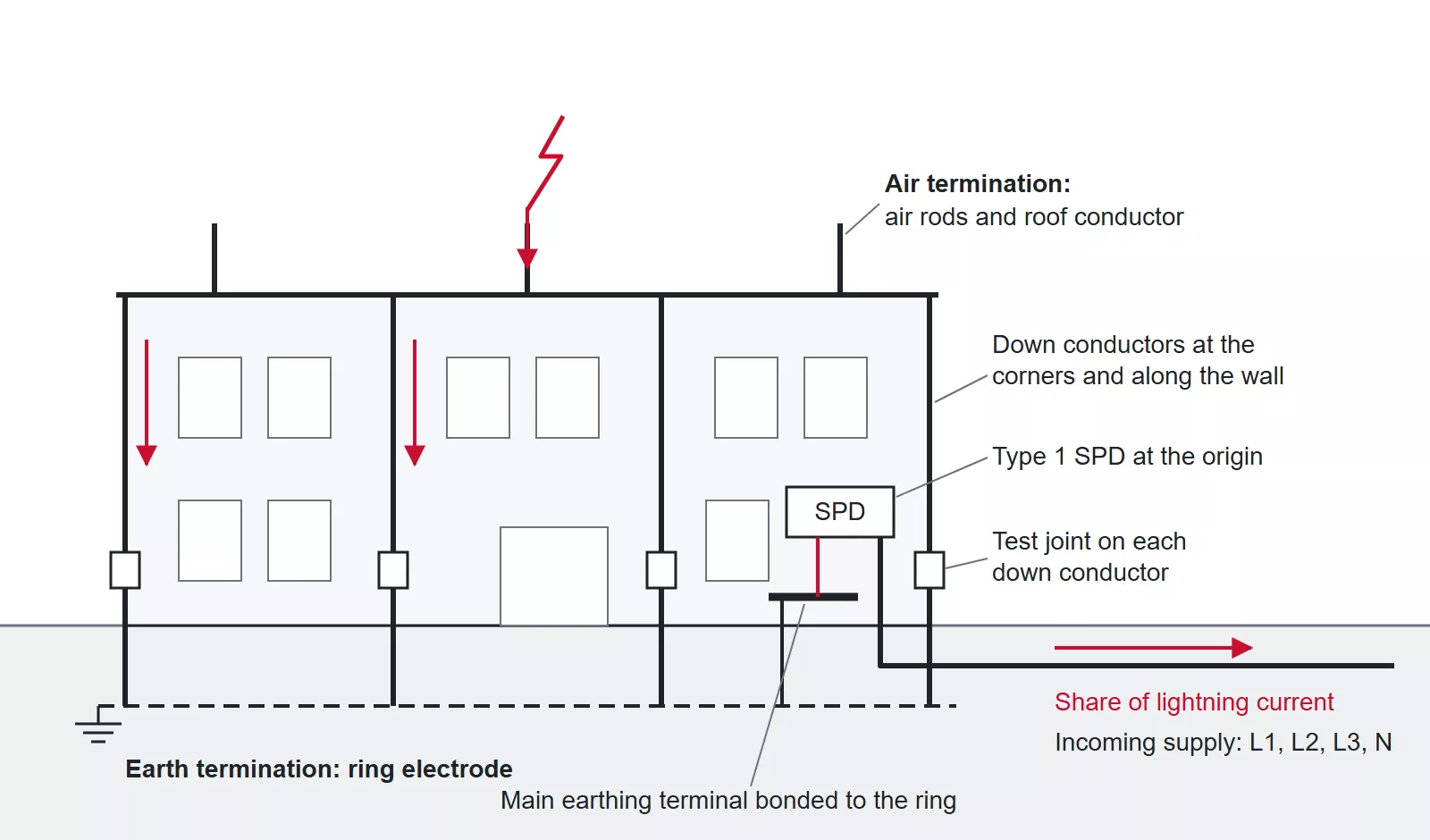
Figure 1 — Air termination on the roof, down conductors at the corners with test joints, the earth termination, and the share of lightning current that leaves through the incoming supply.
Down conductor and air termination sizes
IEC 62305-3 sizes air-termination conductors and down conductors from the same table, so one set of numbers covers the roof and the walls. The values below follow the 2010 edition, which most specifications still cite. If a project names the 2024 edition, check the dimensions against it.
| Material | Solid tape | Solid round | Stranded |
| Copper or tin-plated copper | 50 mm² | 50 mm² | 50 mm² |
| Aluminium | 70 mm² | 50 mm² | 50 mm² |
| Aluminium alloy | 50 mm² | 50 mm² | 50 mm² |
| Hot-dip galvanised steel | 50 mm² | 50 mm² | 50 mm² |
| Stainless steel | 50 mm² | 50 mm² | 70 mm² |
Two entries break the 50 mm² pattern. Plain aluminium tape needs 70 mm², while aluminium round bar and stranded conductor stay at 50 mm², so a specification that accepts 50 mm² aluminium tape is undersized. Stranded stainless steel also needs 70 mm², even though solid stainless tape and round bar stay at 50 mm².
Free-standing air rods are a separate case. They are sized for wind load, so the standard asks for 176 mm², roughly a 15 mm diameter rod, in copper, aluminium alloy or steel.
How many down conductors you need
A non-isolated LPS needs at least two down conductors, spread around the perimeter, with the corners as the first positions. Beyond that, the class of LPS sets the preferred spacing between them: 10 m for Class I and II, 15 m for Class III and 20 m for Class IV. The standard calls these preferred values. A doorway or a run of glazing can push one down conductor a little off the grid, and that is accepted as long as the distribution around the building stays even.
Dividing the perimeter by the spacing gives a starting estimate; the real count comes from placing them side by side. A 40 m × 25 m warehouse has a 130 m perimeter, and at Class III 130 ÷ 15 suggests about nine. Put one at each corner, then divide each side: each 40 m side needs two more to bring the gaps down to about 13 m, and each 25 m side needs one more for gaps of 12.5 m. That layout uses ten down conductors. The same building at Class II, with 10 m spacing, comes to fourteen.
Isolated air terminations count differently. Each free-standing mast needs at least one down conductor, and a steel mast, or a concrete mast with continuous reinforcement, already is one. A building with an enclosed courtyard more than 30 m around also needs down conductors inside the courtyard.
Routing, test joints and the base of the run
A down conductor should read as a continuation of the roof conductor: straight down the wall, by the shortest route, from the air termination to the earth termination. Lightning current rises in microseconds, so the inductance of the run matters more than its resistance. Every extra metre and every bend adds voltage along the conductor, and that voltage is what drives a flashover to wiring or pipework inside the wall.
The practical rules follow from that:
- Run vertically and avoid loops. Where a parapet or overhang forces one, the gap across the loop has to be wider than the separation distance.
- Keep down conductors out of gutters and downpipes, even when the conductor is insulated.
- Route clear of doors and windows wherever the façade allows.
- Fix at roughly 1 m intervals. Rigid galvanised steel tolerates slightly wider spacing between holders; aluminium needs the full 1 m.
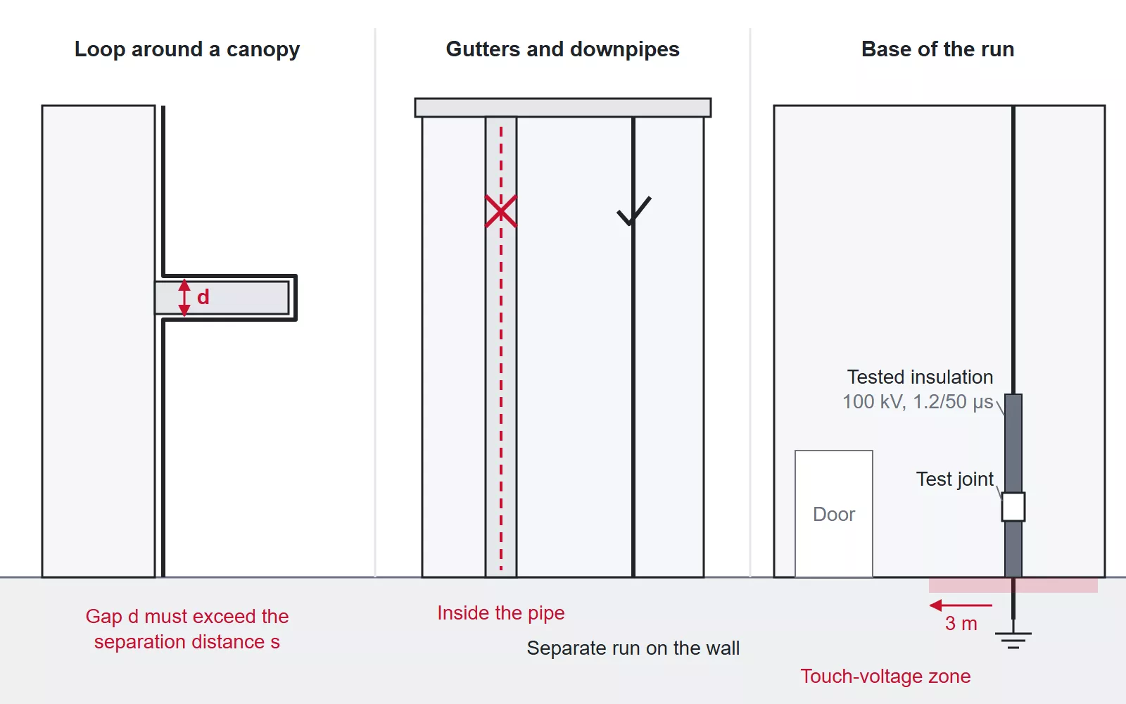
Figure 2 — Down conductor routing: the gap across a loop around a canopy, a run inside a downpipe versus a separate run on the wall, and the test joint, tested insulation and 3 m touch-voltage zone at the base.
A reinforced concrete or steel-framed building may not need external down conductors at all. Steel columns and reinforcement can serve as natural down conductors if they are electrically continuous, and IEC 62305-3 accepts reinforcement when the resistance from the top of the structure to ground level is 0.2 Ω or less. That has to be designed in and measured during construction, so the decision belongs at the design stage.
Each down conductor gets a test joint where it connects to the earth termination, so the electrode can be disconnected and measured during inspection. The joint stays closed in service and opens only with a tool. Natural down conductors tied into a foundation earth electrode are the exception, because there is no separate electrode to disconnect.
The base of the run is where people can touch it. During a strike the bottom few metres of a down conductor rise to a high voltage relative to the ground a person stands on, and IEC 62305-3 treats the area within 3 m of it as a touch-voltage hazard. The first fix is routing: keep exposed down conductors away from entrances, waiting areas and footpaths. Where exposure remains, use a tested touch-protection arrangement with an impulse withstand of 100 kV (1.2/50 µs), usually built around 3 mm of cross-linked polyethylene, a high-resistivity surface such as asphalt or a deep gravel layer, or barriers and warning notices. A plain sleeve or protective tube over a bare conductor falls short of this, because wet surfaces and discharge creeping along the insulation can still bring the voltage to a hand.
When roof metal can be the air termination
Metal already on the roof can take the strike in place of added conductors. Roof sheeting, parapet capping, railings and roof-level steelwork can all act as natural air terminations, and on a large metal roof they can replace most of the mesh. For sheeting, the first test is thickness:
| Sheet material | Puncture must be prevented | Puncture acceptable |
| Steel (galvanised or stainless) | 4 mm | 0.5 mm |
| Copper | 5 mm | 0.5 mm |
| Aluminium | 7 mm | 0.65 mm |
Most profiled roof sheet is under 1 mm, so in practice it qualifies only where a hole burnt through at the attachment point is acceptable: nothing flammable directly beneath it, and no water ingress that would matter. Where puncture must be prevented, a thin roof needs its own air termination above it. The thicker column covers puncture. Whether the underside stays cool enough is a separate question, which the 2024 edition of IEC 62305-3 treats as its own check, so a sheet over combustible insulation or stored goods needs that check too.
Thickness is only half the test. The sheets also need durable electrical continuity between them, through welded, riveted or bolted laps and never through paint or sealant, plus a proper connection into the down conductors. Railings and parapet capping are judged as conductors, on their own cross-section and joints, and the sheet table does not apply to them. Where the roof metal cannot do the job, add air terminations positioned by the rolling sphere, mesh or protective angle method.
Roof equipment and separation distance
Air-handling units, PV arrays, antennas and cable trays are where most layouts get difficult. Any metal near an air termination or down conductor either stays far enough away that a flashover cannot happen, or it is bonded to the LPS. The required gap is the separation distance, and it grows with the class of LPS and the length of conductor back to the nearest bonding point. Typical results are a few tens of centimetres, which a crowded plant roof often cannot give.
The usual answer is an extra air rod that puts the equipment inside its protected volume while keeping the separation distance from it. Bonding is the alternative, and it changes the electrical design: once the equipment frame is bonded, part of the lightning current can enter the building along that equipment’s cables. A PV array bonded to the LPS needs lightning-current-rated protection on its DC cables, covered in SPD selection for rooftop PV, and the supply and control cables of a bonded air-handling unit need the same thought.
Where the down conductor current goes next
When the current reaches the bottom of the down conductors, it does not all stay in the ground. The earth termination is bonded to the main earthing terminal, and through it to the incoming power cable, the water pipe and any other metal service. The current divides between these paths according to their impulse impedance, and IEC 62305-1 simplifies the split to half into the earth termination and half out through the services.
If the power cable is the only metal service, that half divides across its four conductors (three lines and neutral). The result per conductor is 25 kA (10/350 µs) at LPL I, 18.75 kA at LPL II and 12.5 kA at LPL III and IV. In a 3+1 arrangement the single N-PE spark gap carries all four shares at once, which is 100 kA at LPL I and 50 kA at LPL III and IV. The full working, including what changes when other services share the current, is in how the *Iimp* rating is calculated.
That per-conductor figure is the decision the down conductors hand to the electrical side. At 25 kA, which also covers LPL II, a Type 1 surge protection devices such as the Thor TRS-A25 (Iimp 25 kA, Up ≤2.2 kV) fits each line. At 12.5 kA, a combined Type 1+2 SPD such as the TRS5-B+C in its 275 V version (Iimp 12.5 kA, Up ≤1.3 kV) carries the lightning share and limits the voltage in one device. In a 3+1 board, size the N-PE module separately to the combined figure.
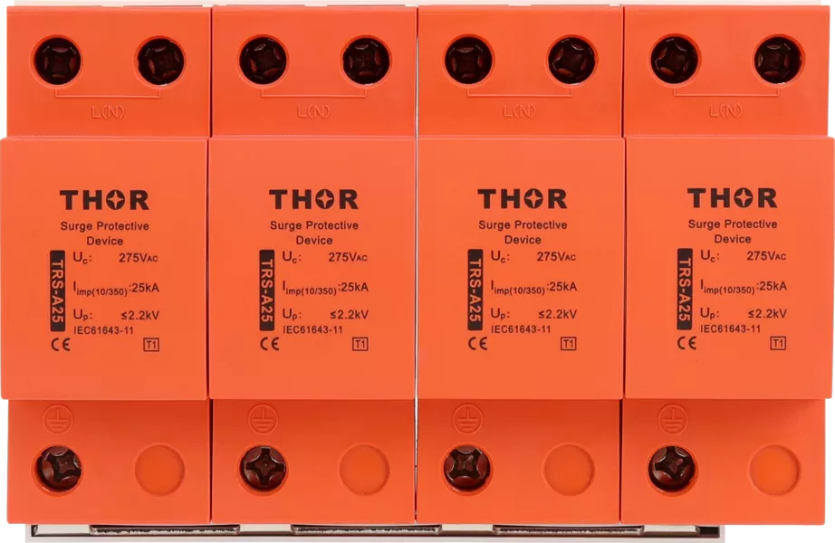 | 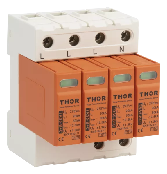 |
Figure 3 — Thor TRS-A25 Type 1 spark gap SPD and TRS5-B+C Type 1+2 SPD.
FAQ
What is the best material for a down conductor?
Copper and aluminium are both standard. Copper suits almost any environment and can continue below ground. Aluminium is lighter and cheaper but must not be buried or set into concrete, so an aluminium down conductor stops above ground and changes to copper or galvanised steel through a bimetallic joint before the earth termination. Galvanised or stainless steel is used where corrosion or theft is the bigger concern.
Can a down conductor run inside a wall or behind cladding?
Yes. Concealed down conductors in a cavity, a conduit or behind façade cladding are common on modern buildings. Where the wall or its insulation is combustible, the conductor heats up during a strike, so it needs clearance from that material or a larger cross-section that keeps the temperature rise safe; a non-combustible conduit on its own does not settle the question. The separation distance to cables and pipes inside the wall still applies, and since the conductor can no longer be inspected along its length, keep joints to a minimum, use connectors tested for lightning current, and leave the test joint accessible.
Is lightning protection a legal requirement in the UK?
Not as a blanket rule. BS EN 62305, the UK adoption of IEC 62305, is the design standard, and whether a building needs an LPS comes from its risk assessment, plus any insurer, client or building-control requirement. Once a system is fitted, it is designed, installed and inspected to that standard.