Surge events destroy CCTV systems in two ways: a direct hit burns out cameras and NVRs instantly, while repeated low-level transients degrade image sensors and storage drives over months until the system fails without warning. Either way, the fix is the same — surge protective devices (SPDs) installed at both ends of every cable run that connects outdoor cameras to indoor equipment.
This guide covers the specific SPD requirements for IP camera systems, analog CCTV, PoE installations, and building-to-building camera runs, with wiring references for each scenario.
Core Strategies for CCTV Surge Protection
A systematic approach is essential for reliable CCTV surge protection. The core of this strategy is the “Protect Both Ends” Mandate. Every conductive cable must be protected where it connects to an outdoor camera and where it terminates inside the building at the head-end equipment. A professional installation accounts for surges originating from either end of the cable run.
Long cable runs act as antennas during nearby lightning events, inducing powerful transient voltages. Protection solely at the recorder leaves the camera electronics vulnerable, and vice-versa. Placing Surge Protective Devices (SPDs) at both ends ensures the system is secured regardless of where the transient voltage is introduced, providing comprehensive protection for the entire circuit.
Technical diagrams clearly illustrate this fundamental concept. Figure 1, for example, shows a camera connected to a building without an external lightning protection system, yet it still requires surge protective devices at both the camera’s junction box and where the cable enters the control room.
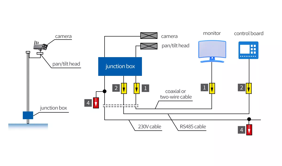
Figure 1 – Camera system connected to SPDs on both ends without external lightning protection system
Understanding the function of an SPD is the second core principle. It is not a wall that blocks energy but a high-speed diverter. Upon detecting a voltage spike, an SPD instantly creates a safe path to redirect the harmful surge current away from sensitive equipment, a mechanism that relies entirely on the grounding system.
Effective grounding: the foundation of CCTV surge protection
The performance of every SPD is entirely dependent on its connection to a verified earth ground. A surge protector requires a low-impedance path to safely dissipate millions of watts of energy from a surge event. Without an effective ground, the entire surge protection system is rendered useless and cannot protect valuable surveillance equipment.
A professional installation achieves this through equipotential bonding. Equipotential bonding connects all system components and their surge protectors to a single, common grounding point. A Main Equipotential Busbar (MEB) often serves as this common point. Figure 2 clearly illustrates how SPDs for power, data, and control lines are tied to a single MEB, creating a unified ground potential.
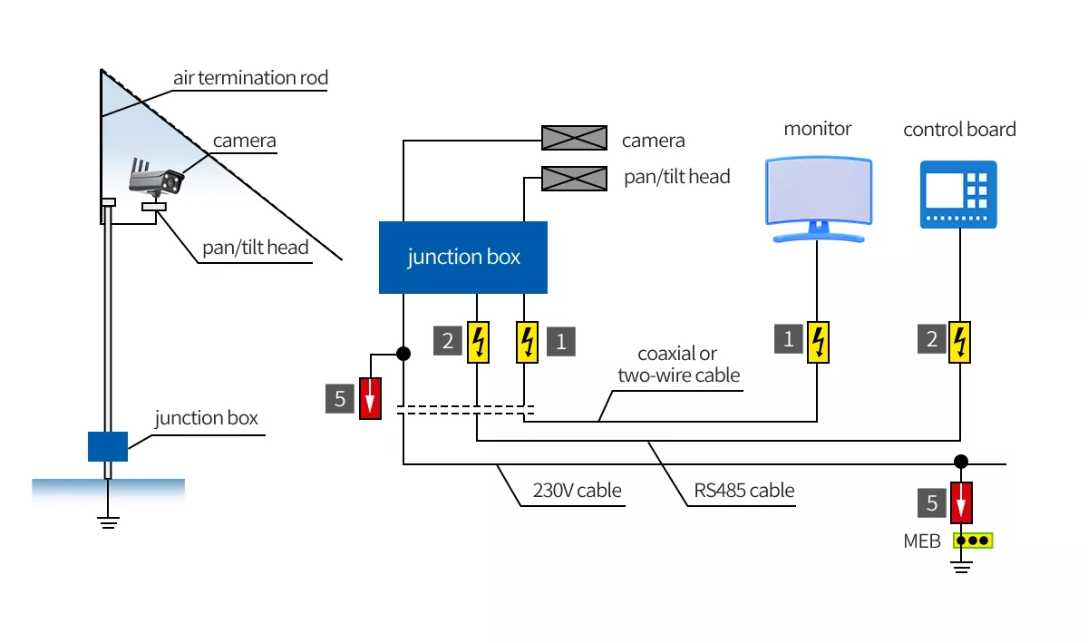
Figure 2 – Camera system connected to SPDs on both ends with external lightning protection system
Adherence to professional installation standards for grounding wires is critical. For fast-rising surges, every inch of wire adds impedance that hinders an SPD’s performance. Grounding connections must always be as short, straight, and direct as possible. Sharp bends or coils in the grounding wire must be avoided as they increase impedance and reduce the effectiveness of the protection.
Implementing a 3-Point Security Camera Protection Plan
To implement strategy into practice, a simple field checklist ensures no critical path is left unprotected. The 3-Point Protection Plan (as shown in figure 3) provides a repeatable, professional framework for every outdoor or exposed camera run. Following this plan methodically guarantees a comprehensive zone of protection for all vulnerable system components from end to end, leaving no weak points.
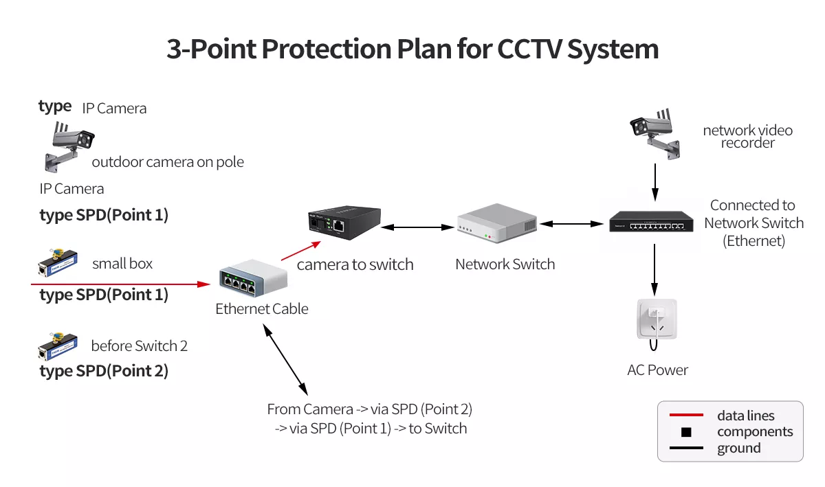
Figure 3 – 3 point protection plan for CCTV systems
- Device-End Protection. A correctly rated SPD for the data and power lines must be installed at the camera’s location. As the most exposed asset, the camera requires this first line of defense against nearby lightning and induced surges. The SPD is typically installed inside a pole base or a NEMA-rated weatherproof enclosure to shield it from environmental factors.
- Head-End Protection. A matching SPD for the corresponding data and power lines is installed where the cable terminates inside the building. Placing the device at the network switch or NVR protects the central hardware—the system’s nerve center—from transients traveling in from the field wiring. A coordinated approach ensures both ends of the line are secured.
- Power Source Protection. A dedicated AC power SPD must be installed to protect the main power circuit supplying the NVR, switch, and other critical head-end hardware. A powerful surge on the building’s main electrical service can destroy the entire system in an instant. Protecting the mains power inlet is a non-negotiable step in any professional installation.
Selecting the Right SPD for CCTV and Surveillance Systems
Choosing the correct Surge Protective Device is critical for both system protection and performance. The specific SPD required is dictated by the type of signal, voltage, and cabling used for the camera.
Surge Protection for IP & PoE Cameras
Modern IP cameras typically require RJ45 Ethernet surge protectors. Selection criteria are crucial: the SPD must be rated for the network’s speed (e.g., Cat6 / 1 Gbps) and the specific Power over Ethernet standard in use (e.g., IEEE 802.3at/af/bt). An appropriate device protects all data pairs and the power feed without impeding performance. Figure 4 is an example of a universal arrester for Industrial Ethernet and PoE applications.
Surge Protection for Analog (HD-over-Coax) Cameras
Analog systems requires a dual-SPD protection approach. The video signal needs a BNC coaxial surge protector like our TRSS-BNC Signal Surge Protective Device. A separate SPD, TRS4 series, correctly rated for the camera’s low-voltage power supply is required for the power lines. Failing to protect both the video and power feeds leaves the camera vulnerable.
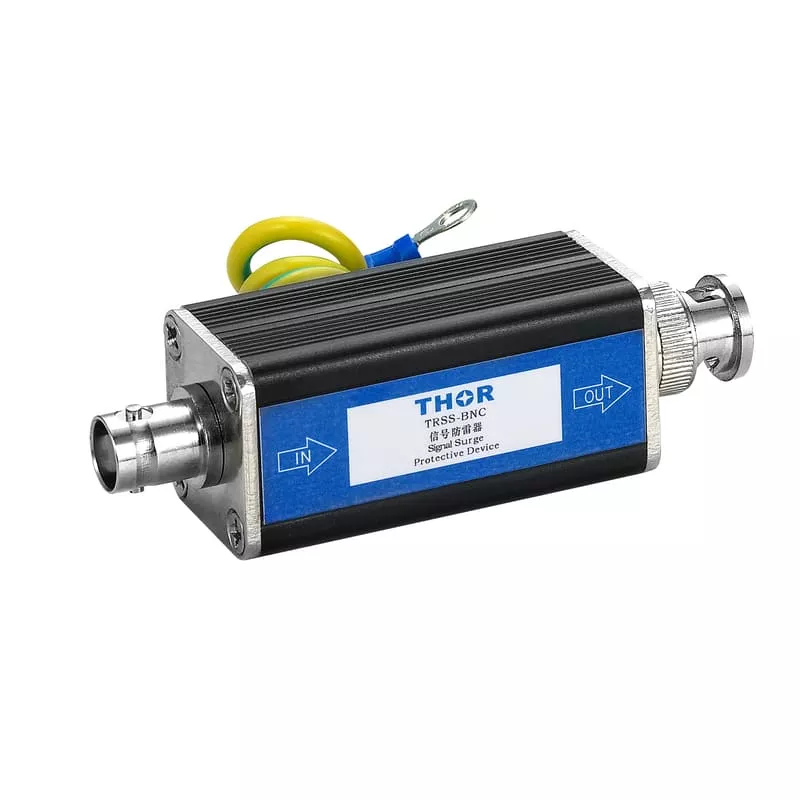 | 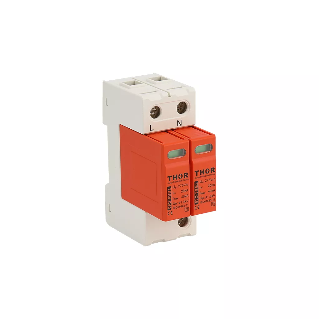 |
| TRSS-BNC Signal Surge Protective Device | TRS4 series Type 2 surge protection device |
Protecting PTZ Camera Control Lines
Pan-Tilt-Zoom (PTZ) cameras often use separate RS485 communication lines for control. If these control lines are run in a separate cable, they must also be protected with dedicated data line surge protectors at both ends of the run. Multi-pair arresters are available for these applications.
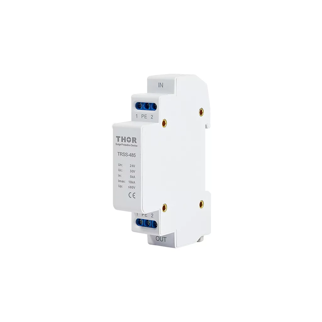
TRSS-485 Control Signal Surge Protective Device
NVR and Head-End Power Protection
The equipment rack is the system’s nerve center and requires AC power protection. High-quality, panel- or rack-mounted AC power SPDs should be installed to protect the circuit supplying the NVR/DVR, network switch, monitors, and all external power supplies.
Best Practices for Surge Protector Installation and Wiring
Meticulous installation practices separate a truly protected system from a vulnerable one. Even the highest-quality SPD will underperform or fail if not installed correctly. The physical mounting, grounding connection, and cable routing are all critical steps that demand professional attention to detail for system’s integrity.
Proper SPD Mounting and Weatherproofing
All outdoor surge protectors must be installed inside a suitable NEMA-rated weatherproof enclosure. Proper housing shields the device and its connections from moisture, dust, and other environmental factors that could compromise performance. For indoor installations, SPDs are often mounted on DIN rails within structured wiring cabinets for clean, serviceable, and organized setups.
Ensuring Grounding Connection Integrity
The grounding connection is the most important physical step in the installation. Use dedicated grounding busbars connected directly to the building’s verified earth ground system. All connections should be made with properly crimped lugs for a secure, low-resistance bond. Daisy-chaining SPD ground connections from one device to another is an unacceptable practice that increases impedance and creates points of failure.
Cable Routing for Surge Mitigation
Surges create powerful electromagnetic fields that can couple onto adjacent wires. To prevent this, physically separate unprotected cables coming from outside from the protected cables running to your equipment. Maintaining this separation helps prevent transients from bypassing the SPD and coupling back into the protected side of the circuit.
CCTV System Maintenance and SPD Inspection
Surge protectors are sacrificial components by design. When an SPD diverts a surge that is large enough, its internal components can degrade or fail completely. An understanding of this finite lifespan is essential for maintaining system reliability over time. SPDs are not “install and forget” devices; they are active safety components that require periodic verification.
To simplify system health checks, it is best practice to select surge protectors that feature a visual status indicator. A common design utilizes a small LED that remains green when the device is fully operational. If the indicator is red or off, it signals that the device has failed and no longer provides protection.
A clear post-event inspection protocol is critical for system uptime. After a significant local electrical storm or a known power grid event, a visual inspection of all SPD status indicators should be performed. Any device indicating a failed state must be replaced immediately. Prompt replacement is the only way to restore full protection before the next transient event occurs.
Conclusion
A comprehensive CCTV surge protection strategy is built on a foundation of solid grounding, a systematic multi-point protection plan, and meticulous, professional installation. An investment in professional-grade surge protection for all signal, control, and power lines is not an optional expense. It is a critical and necessary measure to ensure the long-term performance, reliability, and return on investment of any modern surveillance system, safeguarding the entire circuit from the damaging effects of transient voltage.