
The main difference in AC vs DC SPD selection is the supply each device is designed to protect. AC SPDs serve alternating-current distribution circuits. DC SPDs serve direct-current circuits, with versions designed for solar PV, control supplies and other DC applications. Their voltage ratings, protection paths and fault-disconnection arrangements suit those operating conditions.
For a replacement, choose a device rated for the circuit’s AC or DC application. A product explicitly rated for both can serve either application within its stated limits and wiring conditions.
AC vs DC SPD: the main differences
Both devices limit transient overvoltage and divert surge current. The difference lies in the electrical conditions they must withstand during normal operation, a surge and a fault.
| What to compare | AC SPD | DC SPD |
| Protected circuit | Alternating-current supply | Direct-current supply; PV requires a PV-rated device |
| Common locations | Main board, sub-board, inverter AC output | PV combiner, inverter DC input, suitable DC distribution circuit |
| Voltage marking | AC rating, often expressed as Uc | DC Uc, or Ucpv for PV applications |
| Terminal clues | L, N, PE or phase designations | +, − and PE, depending on the circuit |
| Fault interruption | Designed for the declared AC supply conditions | Needs suitable DC disconnection and fault-current capability |
DC covers a wide range of supplies. A 24 V control circuit needs a device with a low enough protection level for its electronics. A 1,000 V solar array needs a PV-rated device that withstands the array’s maximum operating voltage. The source voltage and the equipment being protected determine the appropriate DC version.
For product selection, compare our AC surge protection devices for low-voltage power distribution and DC surge protection devices for industrial and control power circuits. Each range is designed for its specified operating conditions.
How AC and DC SPDs limit surges and disconnect faults
An AC SPD and a DC SPD may both contain a metal oxide varistor, or MOV. During normal operation, the MOV has high resistance, and the load current follows the normal supply conductors. When a surge raises the voltage, the MOV conducts strongly, creating a parallel path for surge current and limiting the voltage across the protected path.
Fault disconnection is where the supply characteristics become especially important. If a protection element deteriorates or fails, a disconnector may need to separate it from the supply. Opening a current-carrying connection can create an arc. The interruption arrangement must extinguish that arc under the expected fault conditions.
AC current passes through zero periodically, giving the interruption arrangement opportunities to extinguish an arc. Steady DC current continues in one direction, so a DC SPD’s disconnection arrangement must interrupt it under the declared voltage and fault-current conditions. Manufacturers achieve this through product-specific designs, working with external backup protection where specified.
Both surge limiting and safe fault disconnection contribute to the device’s application rating. AC and DC versions can share a DIN-rail housing while using protection circuits and disconnectors suited to their respective supplies.
Can you use an AC SPD on DC, or a DC SPD on AC?
An AC-only SPD and a DC-only SPD should stay in their specified applications. Cross-use is possible with an explicitly dual-rated product: its documentation gives the AC and DC operating limits, permitted protection paths and installation conditions.
For example, Uc 275 V AC describes the device’s maximum continuous operating voltage under the stated AC conditions. For a 220 V DC circuit, look for a declared DC rating that covers the circuit’s actual maximum voltage, together with suitable DC fault-disconnection capability. Use the ratings for the complete device assembly, including its base. An AC-to-DC voltage calculation cannot establish that suitability.
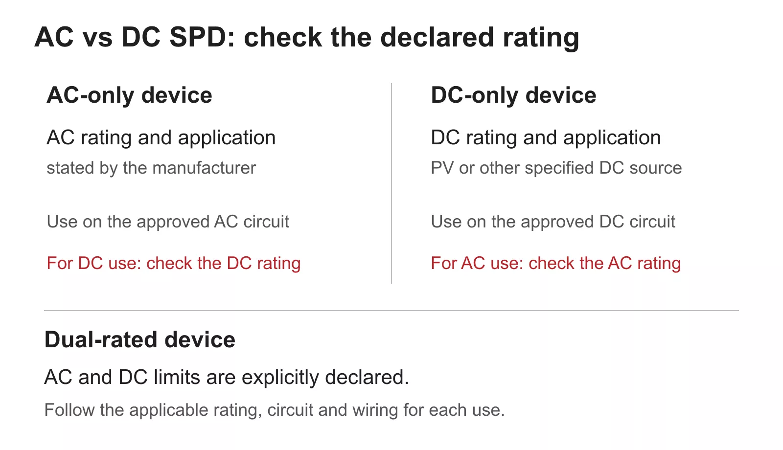
Figure 1 — Select an AC, DC or dual-rated SPD using its declared application and operating limits.
The voltage protection level, Up, also needs to suit the equipment. Low-voltage controls generally need a lower protection level than high-voltage PV equipment, so select the device for both its operating voltage and its protective performance. For a replacement cartridge, use the manufacturer’s compatible series and base with the required electrical ratings.
Which SPD goes on each side of a solar inverter?
A solar inverter connects two different power circuits. The array and inverter input are PV DC; the inverter output and connected distribution board are AC. Where surge protection is required, select the appropriate device for each circuit, as Figure 2 shows.For the solar array side, explore our PV surge protection devices designed for photovoltaic DC applications.
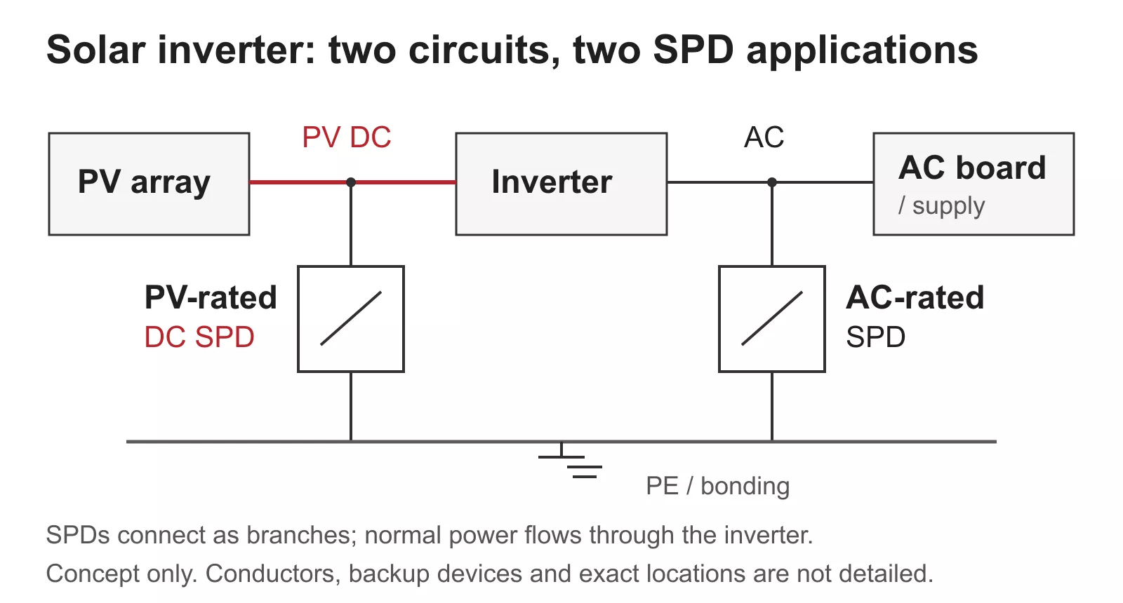
Figure 2 — PV-rated DC protection and AC-rated protection connect to their respective inverter circuits.
The PV device needs a suitable Ucpv for the maximum array voltage, including the rise in open-circuit voltage during cold weather. The AC device needs the appropriate AC voltage rating and protection configuration. Detailed voltage selection belongs in the solar SPD selection guide.
In a hybrid solar system, select protection separately for the PV input and the battery circuit. IEC 61643-31 covers PV-side SPDs. IEC 61643-41 addresses DC low-voltage power systems outside PV applications. For the battery circuit, choose a device specified for that source and its available fault current. The DC surge protection guide covers broader application selection.
What to check before ordering or replacing an SPD
Start with the circuit, then work through the device data:
- Confirm the application. Identify AC distribution, PV DC or another DC source. Check the manufacturer’s stated application and relevant test documentation.
- Match continuous voltage. Use the applicable AC Uc, DC Uc or PV Ucpv. Allow for the circuit’s actual maximum operating voltage.
- Check protection and surge duty. Compare Up with equipment withstand, then select the required Type and discharge-current ratings. Type 1 and Type 2 identify surge-test duties within the appropriate AC or DC family. See how to size an SPD for the detailed process.
- Match the terminals and protection paths to the circuit. Follow the manufacturer’s diagram, including polarity where specified.
- Check fault-current capability, permitted backup protection and replacement-module compatibility. Use Imax for maximum surge-current duty and the applicable short-circuit rating for the source’s available fault current.
Once these checks match, the mechanical details become useful: mounting, conductor capacity and space in the enclosure. Choose the electrical application first, then confirm that the device fits the panel.
Choose the SPD for your circuit
Compare the AC, PV and DC families in the Thor SPD range. For help narrowing the selection, send Thor your circuit type and maximum operating voltage, together with the existing device reference if you are replacing a module.