What Is a DC Surge Protection Device?
A DC surge protection device (DC SPD) clamps transient overvoltages on direct current circuits by diverting surge current to earth. Unlike an AC SPD, it is rated for continuous DC operating voltage and built to interrupt current without the natural zero-crossing that AC waveforms provide. DC SPDs protect solar PV systems, EV charging stations, telecom power supplies, and industrial control circuits.
DC SPDs and AC SPDs run on the same basic principle — a metal oxide varistor (MOV) or similar element conducts when voltage exceeds a set threshold, diverting surge energy to earth. After conduction, the two circuit types behave differently.
On an AC circuit, the supply voltage crosses zero 100 times per second. When the MOV conducts and the surge passes, follow current drops naturally to zero at the next zero-crossing, and conduction stops. On a DC circuit, there is no zero-crossing. Once the MOV begins conducting, supply current flows through it continuously. Without a mechanism to interrupt that current, the MOV overheats and fails — or sustains an arc that becomes a fire risk.
DC SPDs counter this through components and circuit architectures rated for continuous DC operation: higher-grade MOV elements, gas discharge tube (GDT) designs built for DC interruption, or hybrid topologies combining both. The backup overcurrent protective device in series is not optional — it is the interruption mechanism the SPD depends on to clear fault current.
Uc, the maximum continuous operating voltage, is the first parameter to check when selecting a DC SPD. It must sit above the highest voltage the system will reach under any operating condition — including open-circuit voltage on PV strings and regenerative voltages in motor drives. Select below this threshold, and the SPD conducts under normal operating voltage, overheats, and fails within months.
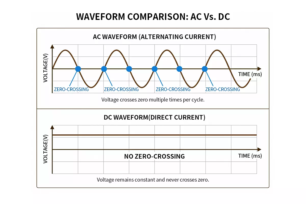
Figure 1 — AC vs DC current waveform: AC sine wave with zero-crossing points highlighted vs flat DC line with no zero-crossing
Why AC SPDs Fail on DC Circuits
Put an AC SPD on a DC bus and the failure mode is predictable.
A standard AC SPD rated at Uc 275V AC carries a voltage withstand test against an AC waveform. The test assumes the device will see 100 zero-crossings per second, any one of which will extinguish follow current. Put that same device on a 275V DC bus and the assumption no longer holds. The MOV conducts, follow current flows, and nothing interrupts it. Internal temperature climbs. The MOV enters thermal runaway and fails short-circuit — not open-circuit. Without a backup fuse or breaker rated for DC interruption, the result is a sustained arc across the supply terminals.
Arc interruption on DC is harder than on AC for a second reason: DC arcs are self-sustaining. An AC arc extinguishes at every zero-crossing because the driving voltage momentarily drops to zero. A DC arc has a constant driving voltage behind it. Once established, it requires active interruption — either a current-limiting fuse rated for DC service or a circuit breaker with a DC breaking capacity rating. Standard AC breakers are not rated for this duty. At 1000V DC, an AC-rated breaker may fail to interrupt the arc entirely.
IEC 61643-31 , the standard governing SPDs for photovoltaic systems, and IEC 61643-11, which covers AC SPDs, are separate documents for this reason. The test waveforms, the Uc verification method, and the backup protection coordination requirements differ in ways that matter in the field. An SPD without a DC-specific standard on its certification label has not been tested for DC arc interruption, regardless of what its voltage rating says.
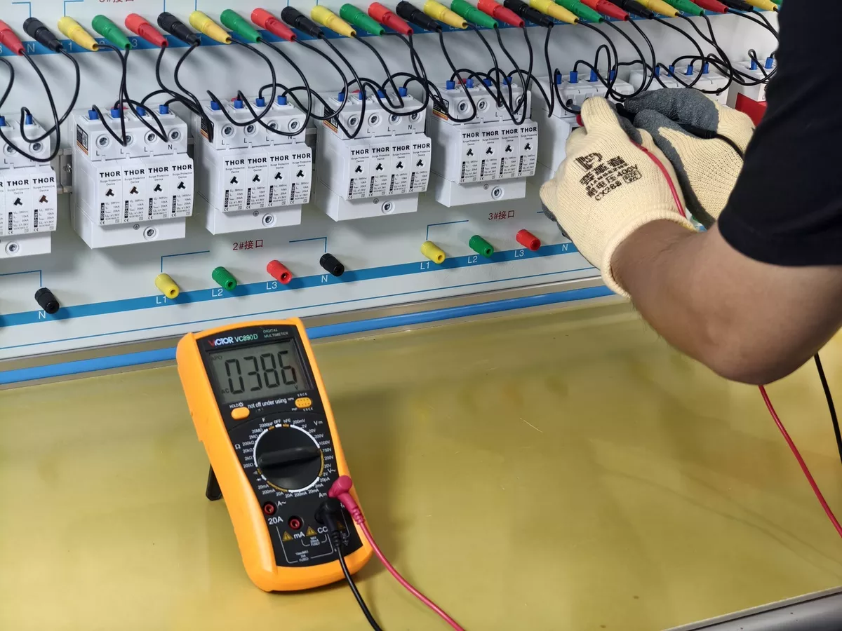
Figure 2 – Voltage reading at 385V AC during SPD aging validation on Thor test bench
For EV charging stations, IEC 61851-23 extends this logic to the DC output side of the charger. The standard’s surge protection guidance references a protection level of Up ≤ 2.5 kV at the DC dispenser — a requirement an AC-tested SPD cannot reliably meet under DC fault conditions.
If the circuit carries DC, the SPD certification must reference a DC standard.
Where DC SPDs Are Used
DC surge protection covers four distinct application areas, each with different voltage levels and exposure profiles.
Solar PV Systems
String cables running 100–300 metres across open ground are effective antennas for lightning-induced electromagnetic pulses. The DC combiner box, positioned between PV strings and the inverter DC input, is the primary installation point. For rooftop systems without an external lightning protection system, a Type 2 PV SPD is standard. Ground-mount installations in high-keraunic zones require Type 1+2. Thor’s TRS3-C40 covers Ucpv from 600V to 1800V DC, certified to IEC 61643-31. For a full treatment of PV-side SPD selection, the surge protection device for solar panels guide covers Type 1 vs Type 1+2, combiner box placement, and lead length rules.
EV Charging Stations
DC fast chargers operate at output voltages from 200V to 1000V DC depending on the charging standard. IEC 61851-23 sets the framework for DC EV charging station protection, with Up ≤ 2.5 kV referenced at the DC dispenser output. AC-side and DC-side protection are separate requirements — a Type 2 AC SPD at the supply entrance does not substitute for a DC SPD at the charger output. The DC SPD must be rated for the charger’s continuous DC operating voltage and tested for DC arc interruption.
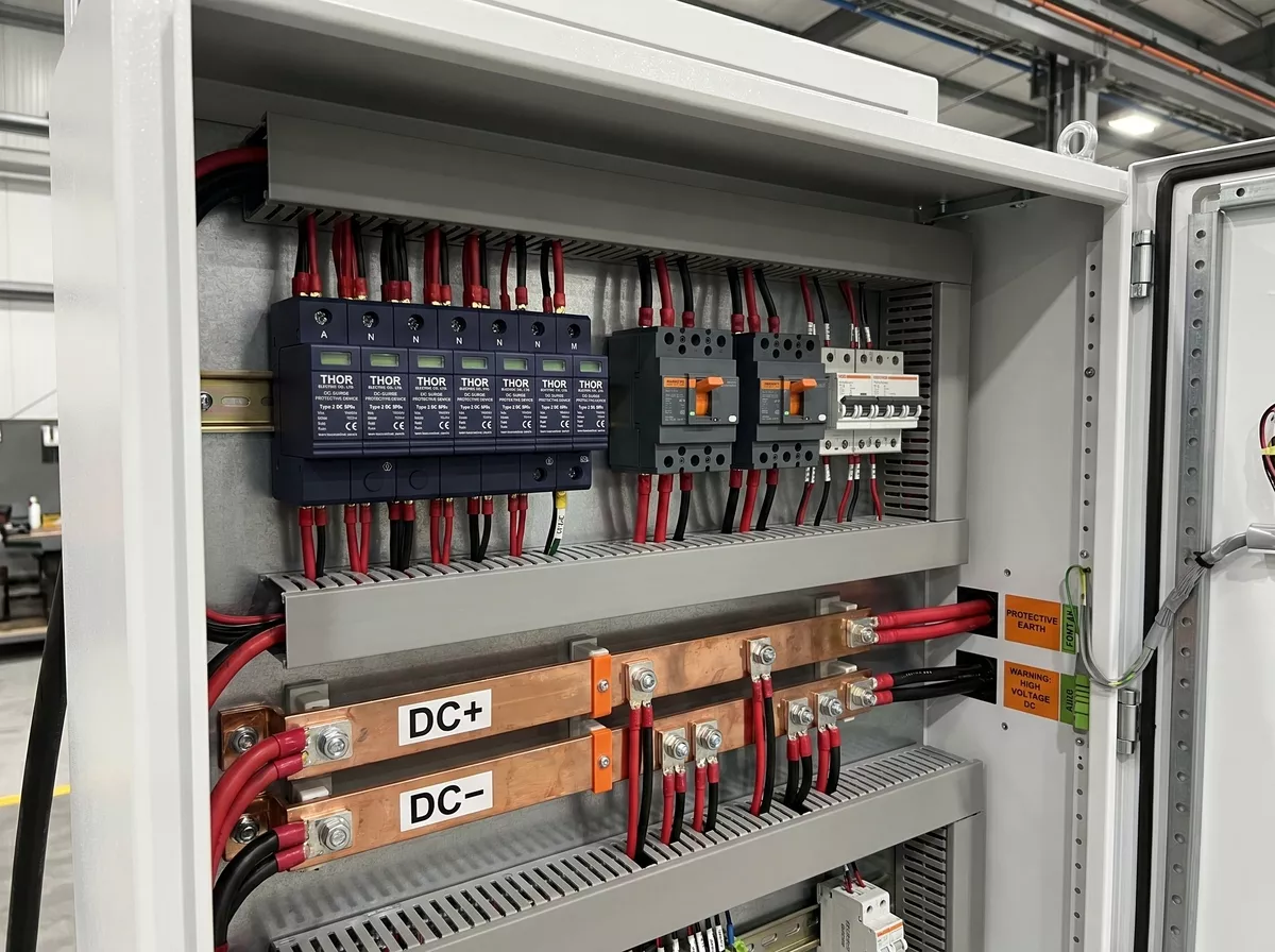
Figure 3 — DC fast charging station showing AC supply input and DC output connection points
Telecom and Data Infrastructure
Most telecom base stations and data centre power plants run on a 48V DC bus — the standard rectified supply for rack-mounted equipment. Surge exposure comes from conducted transients on the AC feed and from cable runs connecting outdoor antennas or remote equipment. Thor’s TRS3 series covers Uc from 36V to 180V DC, with In 20kA and Imax 40kA, for 24V to 110V nominal systems.
Industrial DC Control Circuits
Factory automation and process control systems commonly use 24V DC for sensors, actuators, and PLC I/O. Control cabinet wiring running between buildings or through areas exposed to switching transients from variable-speed drives needs SPD protection at the cabinet entry point. At 24V, Up must stay below the impulse withstand level of the PLC input — typically 500V or less for modern industrial equipment. Thor’s TRS3 at 24V nominal delivers Up ≤ 0.6 kV, well within that threshold.
Key Parameters for Selecting a DC SPD
Four parameters determine whether a DC SPD is correctly specified for a given application. Getting any one of them wrong produces either a device that fails under normal operating conditions or one that lets damaging transients through.
| Parameter | What It Means | Selection Rule |
| Uc | Maximum continuous operating voltage | Must exceed system peak voltage under all conditions |
| In | Nominal discharge current (8/20µs, 15 impulse test) | Minimum 20kA for most industrial and EV applications |
| Imax | Maximum discharge current (8/20µs, single impulse) | Minimum 40kA for exposed outdoor installations |
| Up | Voltage protection level — residual voltage across SPD during surge | Must stay below equipment impulse withstand voltage |
| Iscpv | PV short-circuit current withstand | PV systems only — must exceed string Isc at STC |
Maximum Continuous Operating Voltage (Uc)
Uc is the parameter most often underspecified. For PV systems, Ucpv ≥ 1.1 × Voc(STC) × temperature correction factor — silicon cells produce higher open-circuit voltage as temperature drops. A string measuring 1000V at 25°C may reach 1100V on a cold morning; Thor’s TRS3-C40 specifies Ucpv = 1200V DC against that 1100V minimum.
For non-PV systems, the same margin logic applies. A 48V telecom bus reaches 56–60V during charging cycles — an SPD specified at exactly Uc 48V conducts continuously, overheats, and fails within months. Thor’s TRS3 series specifies Uc 65V for 48V nominal systems.
All Thor Electric DC SPDs are validated on an in-house aging test bench before release. See Figure 4 below.
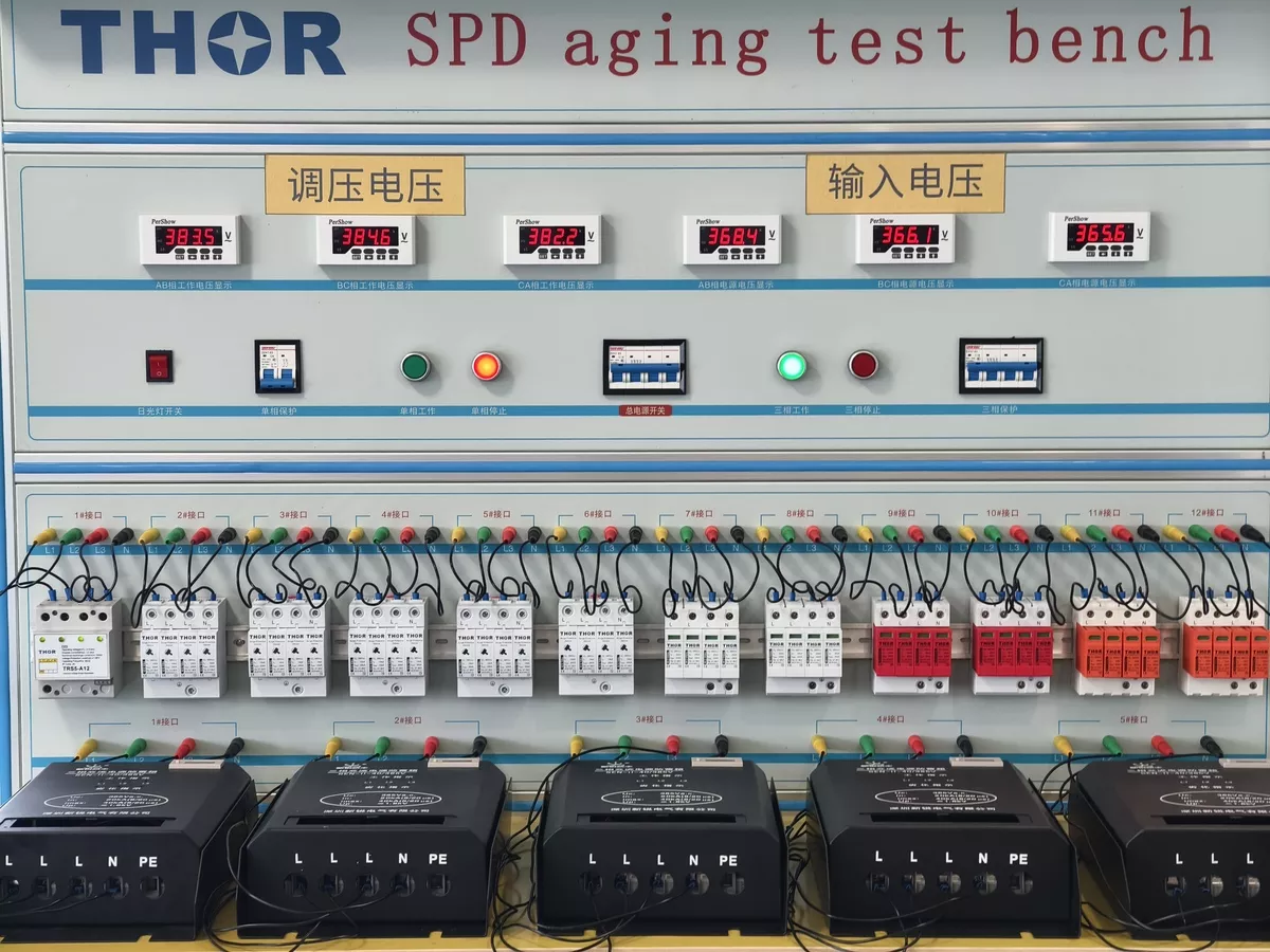
Figure 4 — Thor Electric SPD aging test bench running simultaneous load tests across multiple SPD models
Voltage Protection Level (Up)
Up is the residual voltage the protected equipment sees during a surge. It must sit below the equipment’s impulse withstand voltage. For EV charging stations, IEC 61851-23 references Up ≤ 2.5 kV at the DC dispenser output. For industrial PLC I/O rated at 500V impulse withstand, Up must stay below that threshold — at 24V DC, Thor’s TRS3 delivers Up ≤ 0.6 kV.
Nominal and Maximum Discharge Current (In / Imax)
In is the current the SPD handles repeatedly without degradation. Imax is the single-event ceiling. For Type 2 DC SPDs in commercial and industrial applications, In 20kA and Imax 40kA covers the majority of installations. Thor’s TRS3-C40 meets both figures, certified to IEC 61643-31.
Short-Circuit Current Withstand (Iscpv) — PV Systems Only
On PV circuits, the SPD may be exposed to continuous short-circuit current from the array if it fails short-circuit. Iscpv defines how much of that current the device can withstand without catastrophic failure. Thor’s TRS3-C40 specifies Iscpv 10kA. The Iscpv parameter does not apply to EV, telecom, or industrial DC applications.
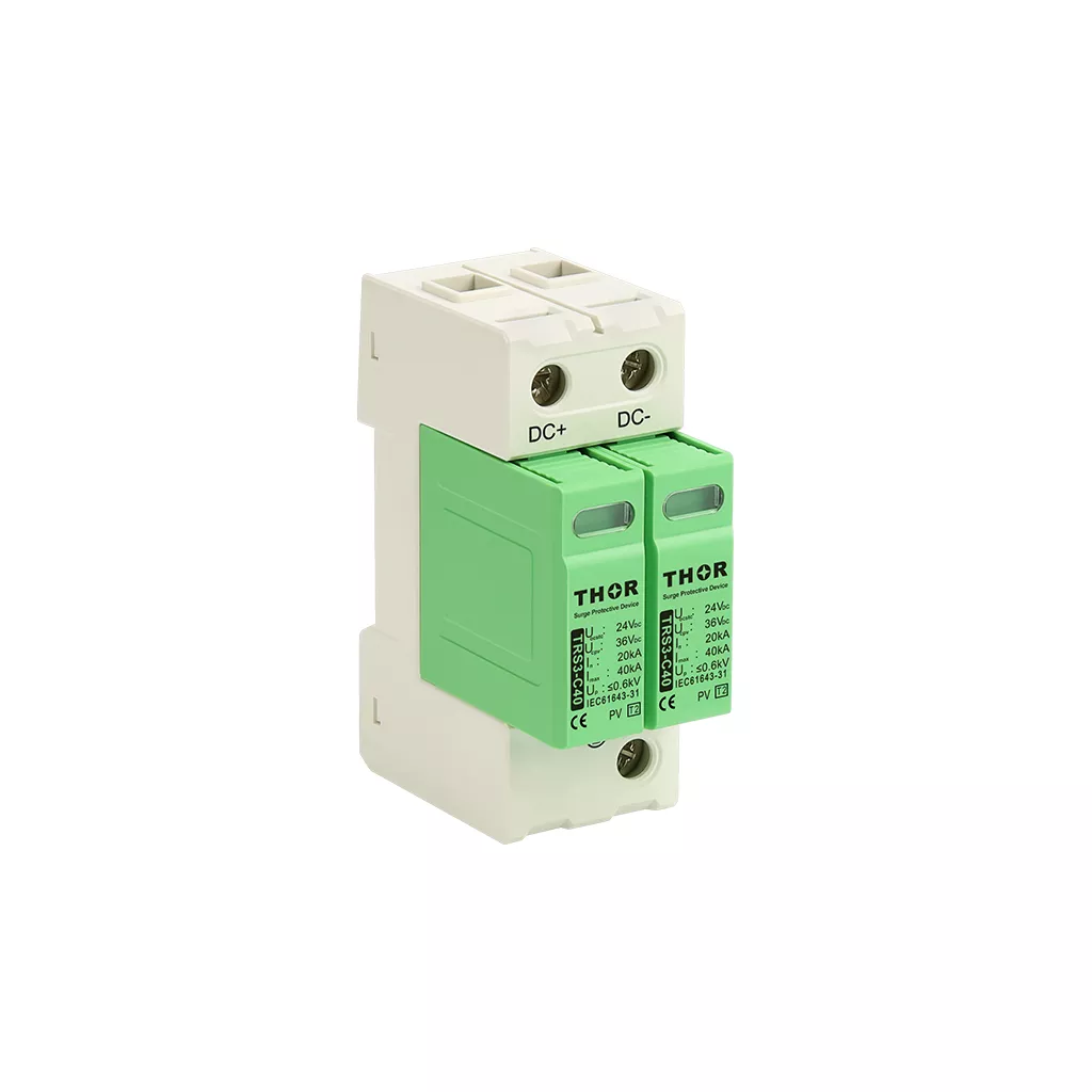
Figure 5 — TRS3-C40 specification label showing Ucpv, In, Imax and Up ratings
DC SPD Wiring: U-Type and Y-Type Connections
DC SPDs connect in one of two configurations depending on system voltage and earthing arrangement. The wrong wiring mode reduces protection to one pole while leaving the other exposed.
U-Type Connection (Standard Bipolar)
The U-type connection places protection on both DC poles independently: DC+ to PE and DC– to PE through separate MOV elements. U-type is the standard configuration for most DC systems — telecom 48V buses, industrial 24V control circuits, EV charging DC outputs, and lower-voltage PV systems up to 600V DC.
As shown in Figure 6, both poles reference the same earth point. A surge appearing on either DC+ or DC– is clamped to PE. The protection level Up applies to each pole independently.
Wiring rule: keep total lead length — line conductor plus earth conductor combined — below 0.5 metres. Each additional metre adds approximately 1µH of parasitic inductance. At a lightning current rise rate of 10kA/µs, that generates 10kV of additional voltage on top of the SPD’s rated Up, negating the protection.
Y-Type Connection (High-Voltage PV Systems)
The Y-type connection is used on PV systems operating above 600V DC, typically 1000V, 1250V, and 1500V string voltages. Rather than referencing both poles directly to PE, the Y-type connects DC+ to PE and DC– to PE through a mid-point earthing arrangement that distributes the voltage stress across the MOV elements.
Thor’s TRS3-C40 supports both U-type and Y-type configurations. U-type covers Ucpv 600V to 960V DC; Y-type covers Ucpv 1200V to 1800V DC. The configuration is determined at the time of order — the connection terminals differ between variants.
Backup Overcurrent Protection
Every DC SPD installation requires a backup fuse or circuit breaker in series, rated for DC service. The backup device must have a DC breaking capacity sufficient to interrupt fault current — standard AC-rated breakers are not suitable. For Thor’s TRS3 series, a 63A gG fuse rated for DC service is the recommended backup. Without it, a short-circuit SPD failure creates a permanent fault across the DC supply.
For wiring diagrams covering both DC and AC SPD configurations, the SPD wiring diagram guide covers single-phase, three-phase, and solar SPD connection diagrams.
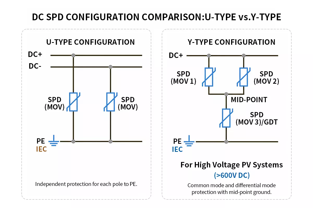
Figure 6 — DC SPD U-type connection (DC+ and DC– to PE) and Y-type connection side by side
FAQ
Can I use an AC SPD on a DC circuit?
No. An AC SPD is tested against an AC waveform with 100 zero-crossings per second, which naturally extinguish follow current after each surge event. On a DC circuit, there is no zero-crossing. Once the MOV conducts, follow current flows continuously, driving the device into thermal runaway or sustaining an arc across the supply terminals. An AC SPD on a DC circuit is not a degraded solution — it is a fire risk. Always specify an SPD with a DC-standard certification reference on the label.
How do I size a DC SPD for an EV charging station?
Match Uc to the charger’s maximum DC output voltage, including any regenerative or no-load overvoltage conditions. For CCS and CHAdeMO fast chargers operating up to 1000V DC, Uc must exceed 1000V with adequate margin. IEC 61851-23 references Up ≤ 2.5 kV at the DC dispenser output — verify the SPD’s datasheet confirms this protection level under DC test conditions, not AC. Specify In 20kA and Imax 40kA as a minimum for public fast-charging installations.
What is the difference between a PV SPD and a DC surge protection device?
A PV SPD is a DC SPD built for the specific demands of photovoltaic systems. Beyond standard DC ratings, it adds Iscpv — short-circuit current withstand from the PV array — and must be certified to IEC 61643-31 rather than the general DC SPD standard. A standard DC SPD without Iscpv and IEC 61643-31 certification is not suitable for PV string protection, even if its Uc covers the array voltage. For a full breakdown of PV-side selection, the surge protection device for solar panels guide covers combiner box placement, Type 1 vs Type 1+2, and wiring rules.
What backup protection does a DC SPD need?
Every DC SPD requires a fuse or circuit breaker in series, rated specifically for DC service. Standard AC-rated breakers cannot reliably interrupt a DC arc — their breaking capacity ratings apply to AC fault current only. The backup device must carry a DC voltage and current rating that covers the system parameters. For Thor’s TRS3 series, a 63A gG fuse rated for DC service is the recommended backup. Without it, a short-circuit SPD failure produces a sustained fault across the DC supply with no automatic interruption.
Does DC SPD polarity matter during installation?
For U-type connections, polarity is not critical — DC+ and DC– connect to PE through independent MOV elements, and reversing the connections does not affect protection performance. For Y-type connections used on high-voltage PV systems, polarity matters. The DC+ and DC– terminals connect through a specific mid-point earthing arrangement, and incorrect wiring reduces protection on one pole. Always follow the terminal labelling on the SPD housing and verify against the manufacturer’s wiring diagram before energising.
Thor Electric DC Surge Protection Devices
All Thor Electric SPDs are certified to IEC, TUV, CE, RoHS, CB and ISO standards. The TRS3 series covers DC system voltages from 24V to 1800V, with Type 2 and Type 1+2 variants and optional remote signalling contacts.
All Thor Electric SPDs are certified to IEC, TUV, CE, RoHS, CB and ISO standards — view certificates on our certifications page.
Samples, custom voltage ratings, and OEM configurations are available. Contact the Thor Electric team for project-specific specifications.