Wire an SPD wrong and you don’t just lose protection — you can fail certification compliance and leave equipment exposed to the exact events the device was installed to stop. This guide covers SPD wiring diagrams for single-phase, three-phase, Type 1, and DC/solar systems, plus the IEC installation requirements that separate a working installation from one that looks right on paper.
What Does an SPD Wiring Diagram Show?
A wiring diagram defines two things: which conductors the SPD bridges, and where it sits relative to the upstream overcurrent protective device (OCPD). For AC systems, that means specifying the protection mode — L-PE, N-PE, or L-N — based on the earthing system. For DC and PV systems, it shows the positive, negative, and PE connections, plus whether the installation uses a U or Y connection type.
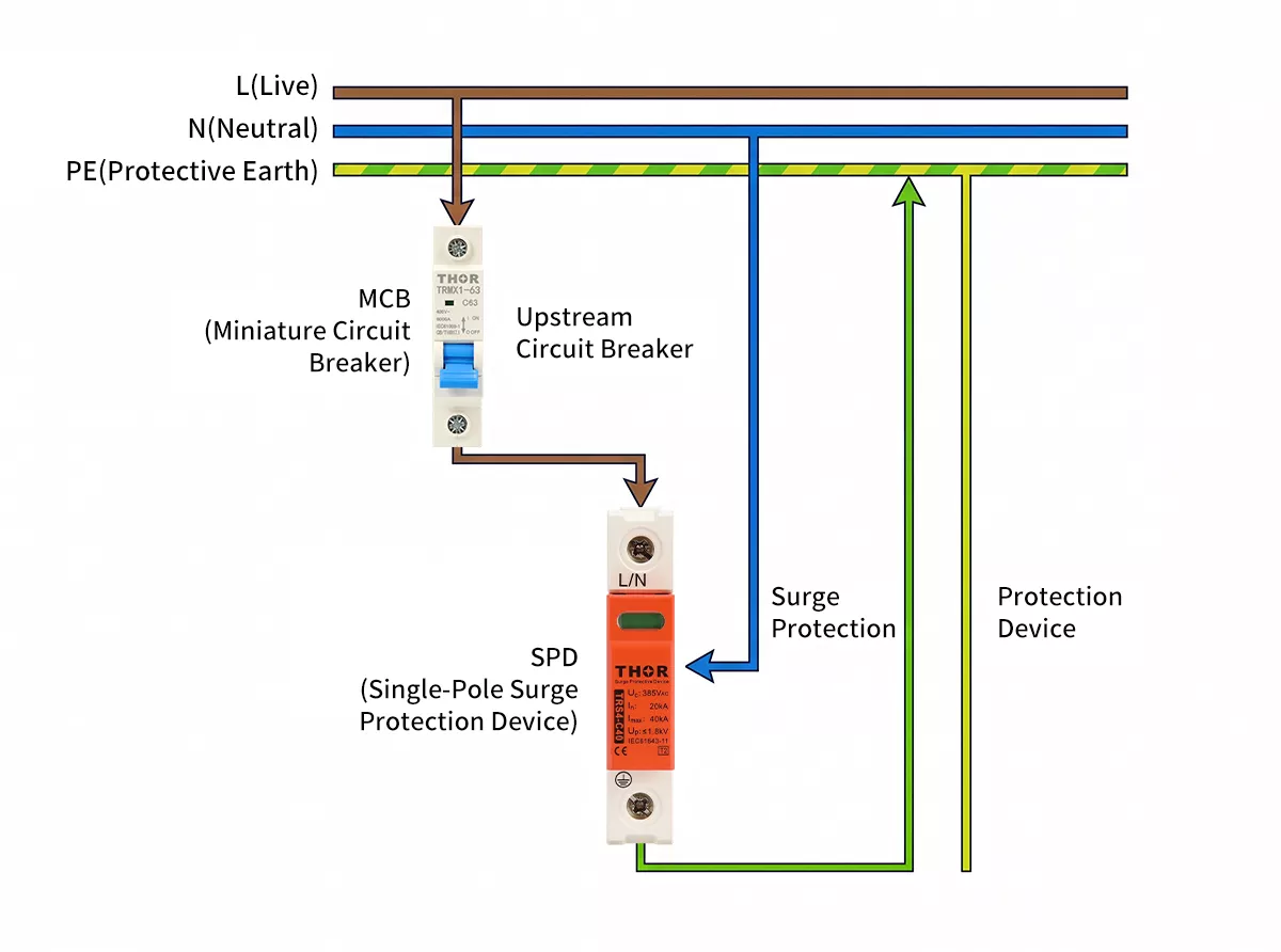
Figure 1: SPD wiring diagram overview showing L, N, PE connections and OCPD placement in a distribution board
The same SPD wired in the wrong mode will either fail to clamp a surge or conduct continuously and trip the OCPD. Neither outcome is useful.
For AC systems, the diagram also indicates the protection mode: L-PE, N-PE, or L-N, depending on the earthing system and SPD configuration. For DC and PV systems, it shows the positive, negative, and PE connections along with the connection type — U or Y — which determines the voltage rating required.
Reading the diagram correctly matters.
Single-Phase SPD Wiring Diagram
Single-phase systems use three conductors: live (L), neutral (N), and protective earth (PE). How the SPD connects across these three determines the protection mode — and the right choice depends on the earthing system in place.
Three connection modes cover most single-phase installations:
2+0 (L-PE and N-PE) is the standard configuration for TN-S systems. The SPD connects both L and N to PE, protecting against surges on either conductor. 2+0 is the most common mode for industrial and commercial single-phase installations in Europe.
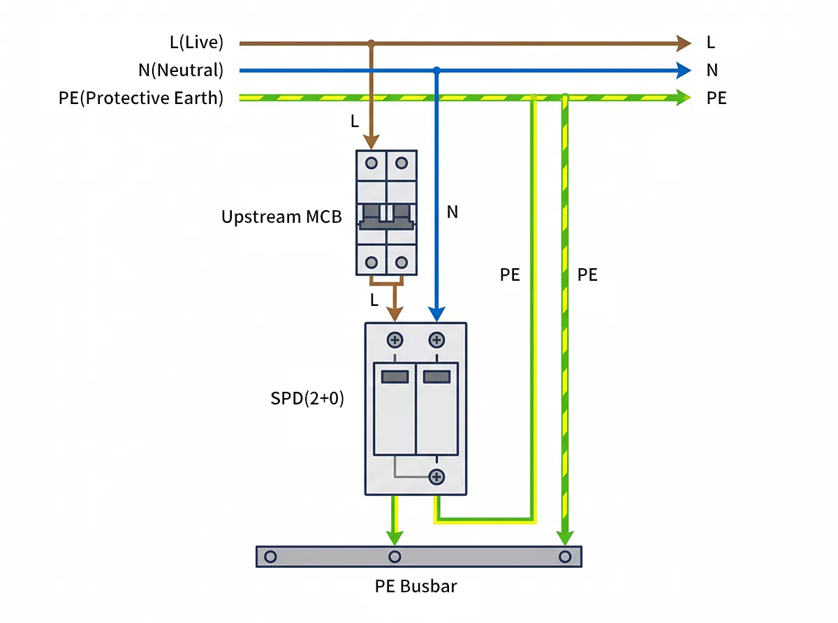
Figure 2: Single-phase SPD wiring diagram showing 2+0 configuration in TN-S system, with L, N, PE connections and upstream MCB
1+1 (L-N and N-PE) suits TT systems where no direct N-PE bond exists at the distribution board. The SPD bridges L to N on one path and N to PE on another, maintaining protection without creating an unwanted earth reference.
1+0 (L-PE only) applies to IT systems or specific single-phase circuits where neutral is not present at the protection point.
For most single-phase installations in TN-S networks, 2+0 is the default. If you’re unsure which earthing system you’re working with, the TN-C-S earthing system article covers the distinctions in detail.
For single-phase T2 protection, the TRS4-C40 (In 20kA, Imax 40kA) covers standard commercial and light industrial loads. Higher-exposure installations — rooftop equipment, outdoor distribution points — step up to the TRS-B60 (In 30kA, Imax 60kA).
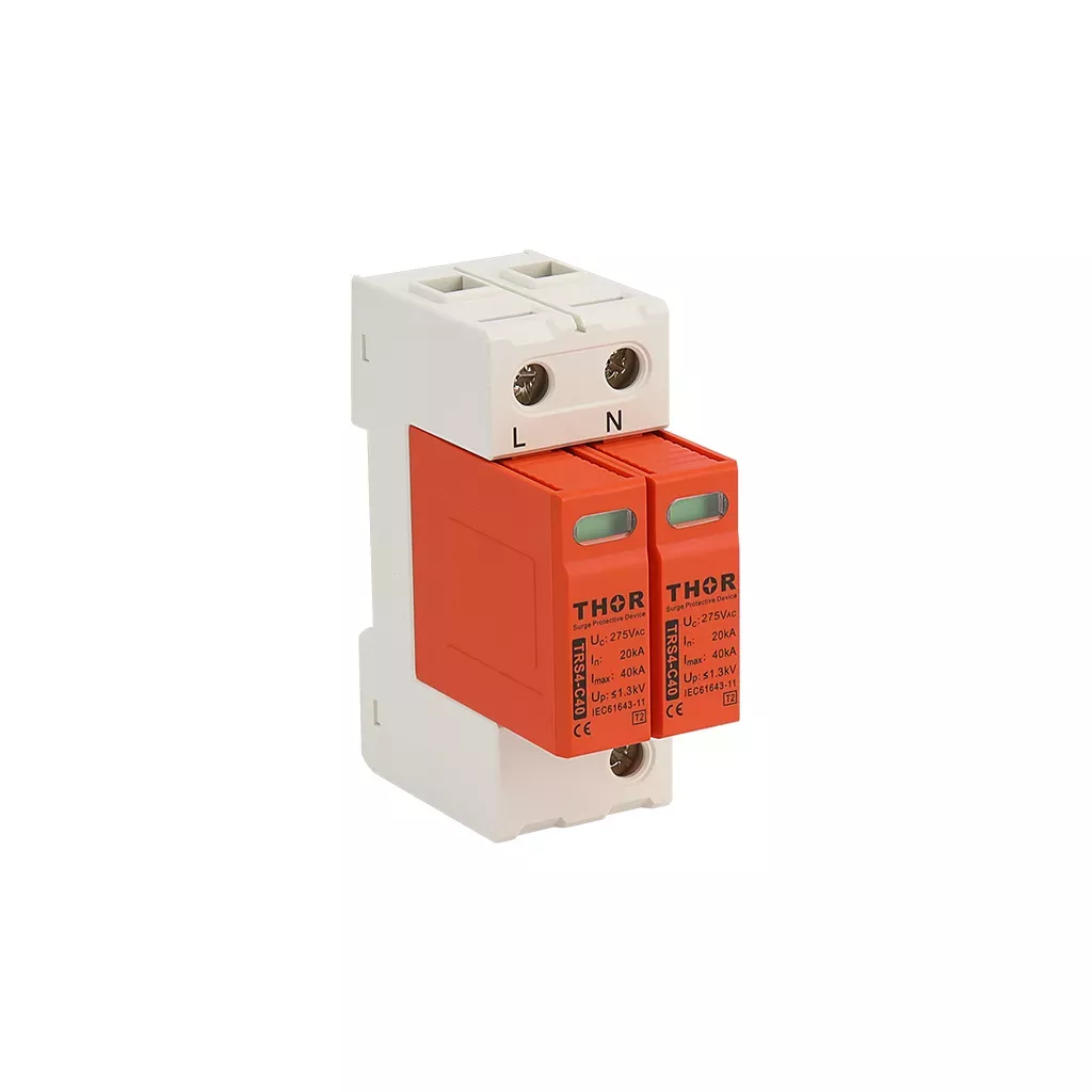
Figure 3: Thor TRS4-C40 single-phase Type 2 SPD product photo
Three-Phase SPD Wiring Diagram
Three-phase systems add L1, L2, and L3 to the picture. The SPD has to protect all three phases simultaneously, which is where the choice between 4+0 and 3+1 becomes critical.
4+0 (L1-PE, L2-PE, L3-PE, N-PE) connects all four conductors directly to PE. Every conductor gets its own protection path. 4+0 is the standard configuration for TN-S systems and most industrial three-phase installations where a separate PE conductor runs throughout.
3+1 (L1-N, L2-N, L3-N, and N-PE) protects the three phases relative to neutral, with a separate N-PE path. The right choice for TT systems where the neutral-earth relationship at the board differs from TN-S. It also applies in installations where the neutral is bonded at a different point in the system.
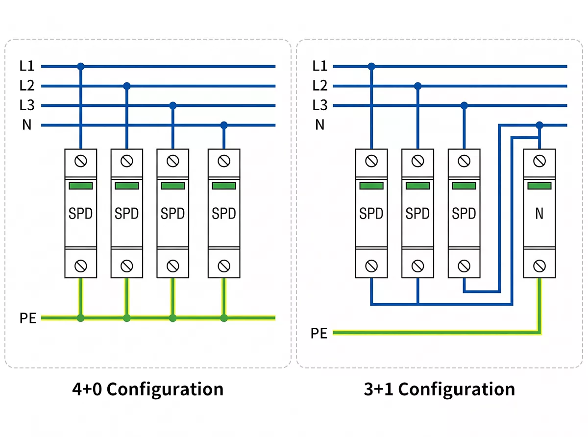
Figure 4: Three-phase SPD wiring diagram comparing 4+0 and 3+1 configurations side by side
Getting this wrong matters. A 4+0 SPD installed in a TT system will conduct on the N-PE path during normal operation — not during a surge — because the N-PE voltage in a TT system isn’t zero. That continuous conduction will eventually destroy the MOV.
For three-phase T2, the TRS7-B80 (In 40kA, Imax 80kA, Un 380V AC) handles standard industrial distribution boards. Sites with higher exposure — main incomer positions, rooftop plant rooms, substations — move to TRS7-B100 or B120.
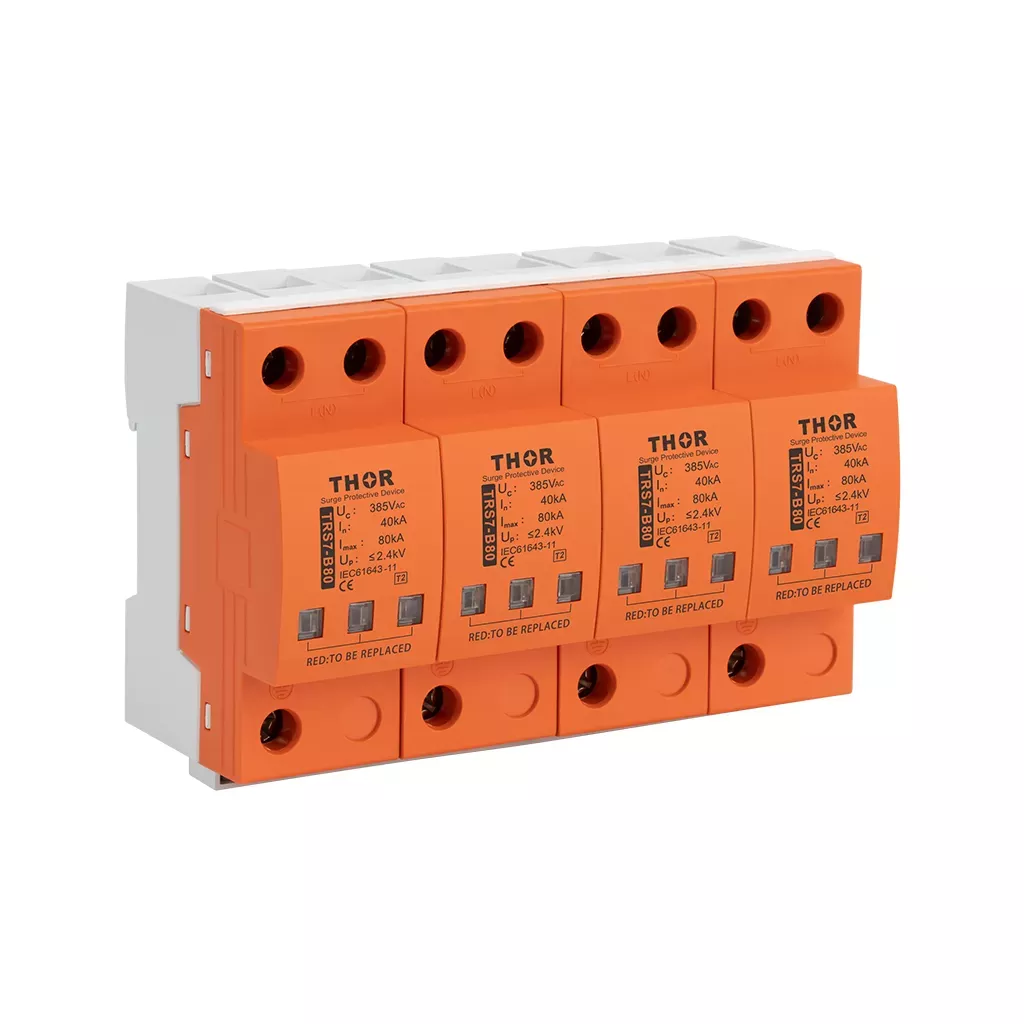
Figure 5: Thor TRS7-B80 three-phase Type 2 SPD installed on DIN rail in distribution board
Type 1 SPD Wiring Diagram
Type 1 SPDs go at the main distribution board — the first point of entry for the incoming supply, before any sub-distribution. The reason is simple: when lightning strikes a building or nearby infrastructure, the resulting impulse current (10/350µs waveform) is too large for a Type 2 device to handle. Only a Type 1 is rated for Iimp, the lightning impulse current parameter.
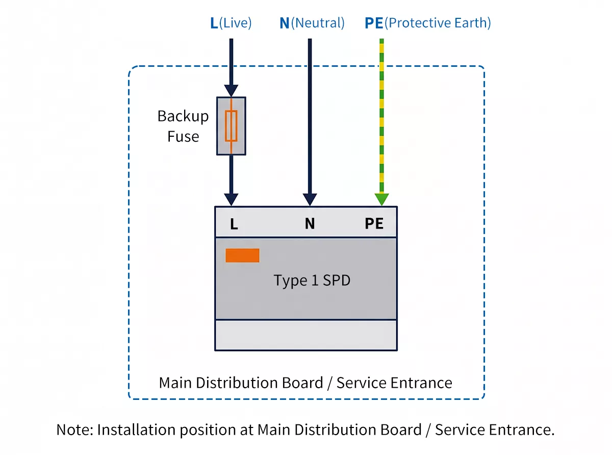
Figure 6: Type 1 SPD wiring diagram showing single-phase and three-phase connections at main distribution board
Physically, the wiring looks similar to Type 2. The SPD still connects between the supply conductors and PE. What changes is the upstream OCPD rating — Type 1 devices carry higher surge currents, so the backup fuse or circuit breaker needs to be sized accordingly, typically 25A or higher depending on the SPD datasheet.
For single-phase Type 1 installations, the TRS-A series uses graphite gap technology rather than MOV. Graphite gap handles the 10/350µs impulse waveform without degrading the way MOV-based devices do under repeated direct lightning exposure. The TRS-A25 (Iimp 25kA) covers most commercial buildings; the TRS-A50 (Iimp 50kA) applies to substations and high-exposure industrial sites.

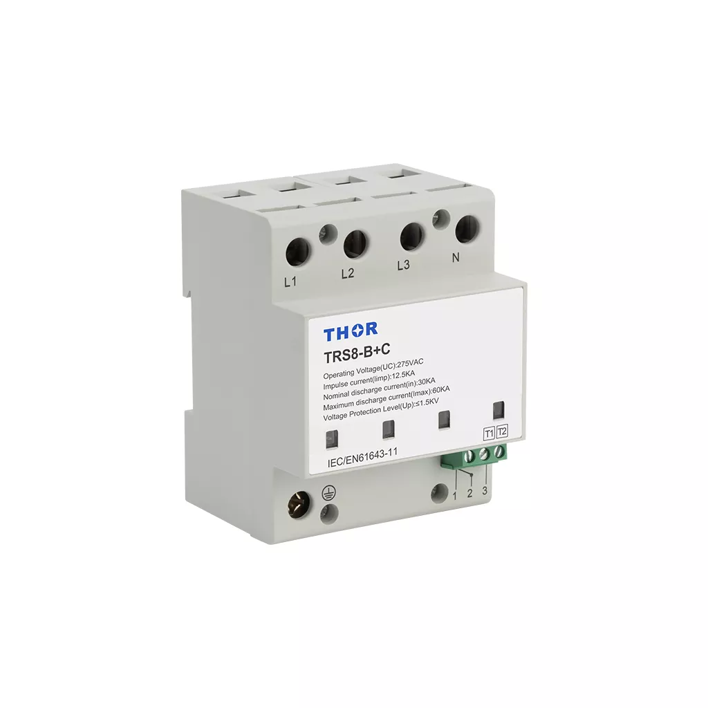
Figure 7: Thor TRS-A25 Type 1 SPD and TRS8-B+C Type 1+2 combination SPD product photo
Where a Type 1+2 combination is needed — common in buildings where the separation distance between the service entrance and first distribution point is short — the TRS8-B+C combines MOV and GDT technology in a single device. Iimp 12.5kA, In 30kA, Imax 60kA. One device, two protection levels, one DIN rail slot.
DC and Solar SPD Wiring Diagram
DC systems don’t alternate. Current flows in one direction only, which changes how an SPD clamps and interrupts a surge — and why DC-rated devices are not interchangeable with AC ones.
For PV systems, two connection types cover the voltage range from small rooftop arrays to utility-scale installations.
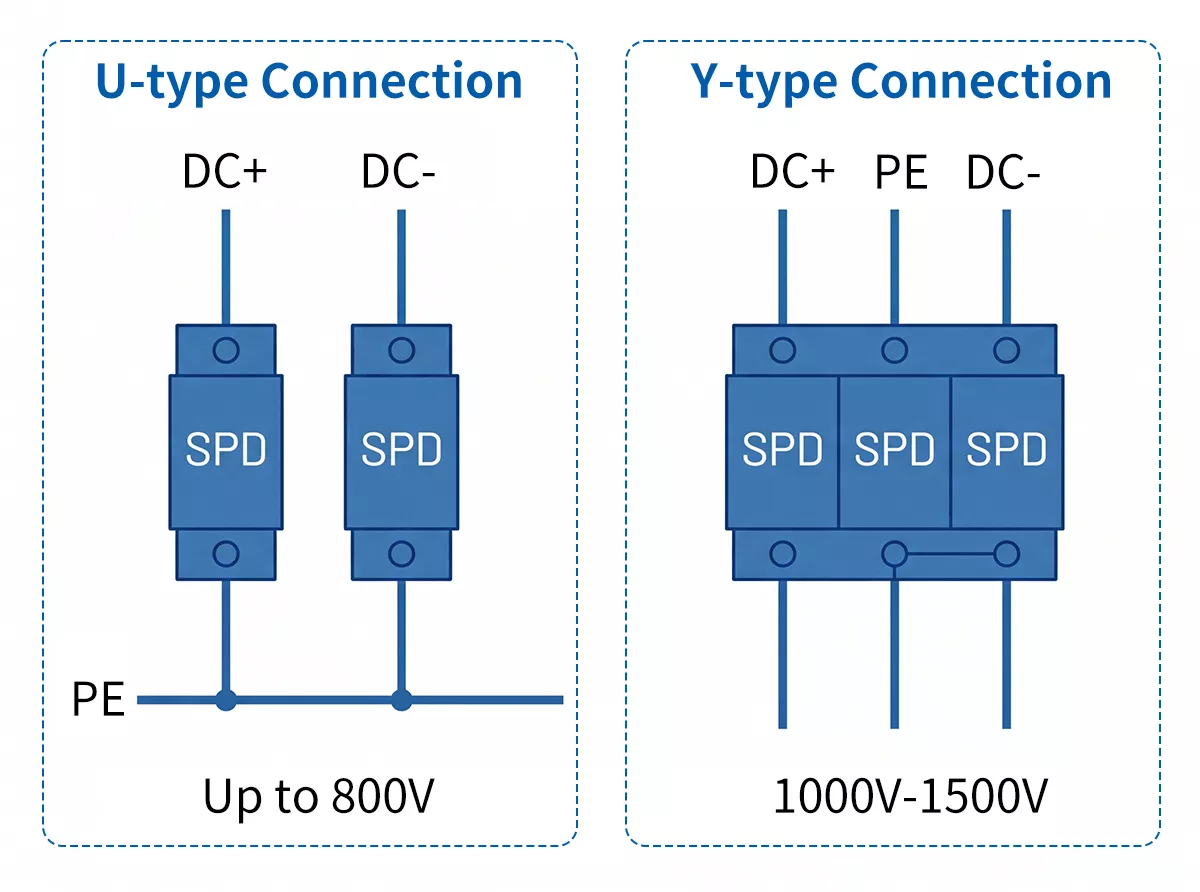
Figure 8: DC and solar SPD wiring diagram showing U-type and Y-type connections for PV systems
U-type connection (DC+ and DC- to PE) is the standard for systems up to 800V Uocstc. Both the positive and negative rails connect to PE through separate MOV paths. Simple to wire, and suits most commercial and industrial rooftop PV installations.
Y-type connection (DC+, PE, DC-) handles high-voltage strings from 1000V to 1500V Uocstc. The PE terminal sits between the positive and negative connections, splitting the voltage across two MOV paths. That split keeps each MOV within its rated voltage while the system operates at string voltages that would exceed a single U-type device.
The TRS3-C40 covers both connection types across the full voltage range:
| Connection | Uocstc | Ucpv | Up |
| U | 500–800V DC | up to 960V DC | ≤3.0kV |
| Y | 1000–1500V DC | up to 1800V DC | ≤6.0kV |
For rooftop PV systems connected directly to a lightning protection system — where IEC 61643-31 requires Type 1+2 capability — the TRS3 High Modules add Iimp ratings of 7kA (1000V) and 5kA (1250V/1500V).
EV charging infrastructure and battery storage systems running on low-voltage DC networks use the same TRS3 platform, available from 24V to 110V nominal with Imax 40kA across all voltage ratings.
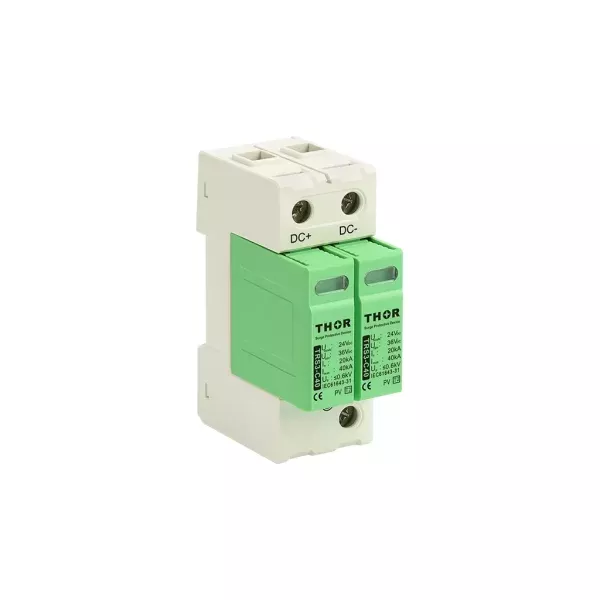
Figure 9: Thor TRS3-C40 PV SPD product photo, green housing, DIN rail mount
How Earthing Systems Affect SPD Wiring
The earthing system in a building determines how neutral and earth relate to each other — and that relationship directly affects which SPD connection mode works and which one causes problems.
Three systems cover most installations globally.
TN-S runs separate N and PE conductors throughout the installation. N and PE are only bonded at the source. At any distribution board downstream, N and PE are distinct. The SPD connects in 4+0 or 2+0 mode — all conductors to PE — because the N-PE voltage under normal conditions is close to zero. No unwanted conduction.
TT has a local earth electrode at the installation, independent from the supply neutral. The N-PE voltage at the distribution board is not zero — it reflects the impedance between the supply neutral and the local earth. A 4+0 SPD in a TT system will see this voltage continuously on the N-PE path and conduct when it shouldn’t. The correct mode is 3+1: phases to neutral, neutral to PE separately, with the N-PE MOV rated for the expected differential.
IT has no direct connection between the supply and earth at all. Used in hospitals, offshore platforms, and some industrial processes where continuity of supply matters more than immediate fault disconnection. SPDs in IT systems connect in 3+0 or 1+0 mode — phases to PE only, no neutral path — because there is no stable neutral reference.
Getting the earthing system wrong at the SPD selection stage is one of the most common installation errors. A correctly rated SPD in the wrong mode will either fail prematurely or provide no protection at all. If the earthing system on site isn’t documented, measure the N-PE voltage at the board before selecting the connection mode.
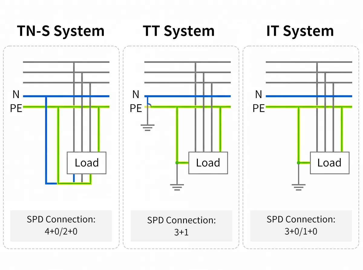
Figure 10: Comparison diagram showing TN-S, TT and IT earthing systems and corresponding SPD connection modes
For a detailed breakdown of how TN-C-S systems work and where the N-PE bond occurs, see the TN-C-S earthing system guide.
SPD Wiring Requirements: What IEC Says
Getting the SPD into the board is only half the job. How the connecting cables are run determines whether the device performs to its rated parameters — or falls short when a surge actually hits.
The 50cm Rule
IEC 61643-11 the total length of the SPD connection leads — L, N, and PE combined — to 0.5 metres. The 0.5m limit isn’t arbitrary. SPD connection cables have inductance, and inductance resists rapid changes in current. During a surge, current rises in microseconds. Every extra centimetre of cable adds inductance that slows the SPD’s response and increases the residual voltage seen by the equipment downstream.
In practice: measure the cable run from the OCPD to the SPD input terminal, then from the SPD earth terminal to the busbar. If the total exceeds 0.5m, the installation is out of spec regardless of what the SPD datasheet says.
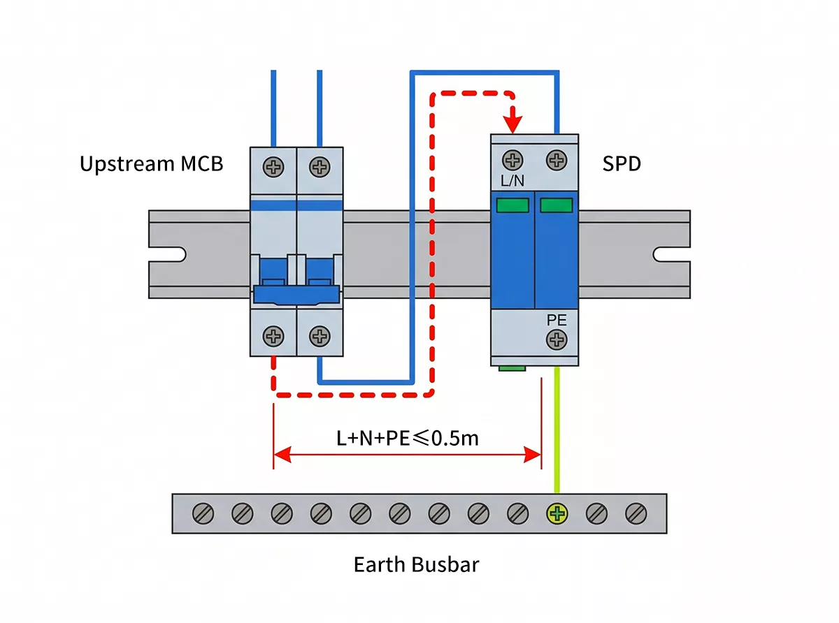
Figure 11: SPD wiring length diagram showing the 50cm rule — total lead length L + N + PE must not exceed 0.5m
Conductor Sizing
The SPD connection conductors need to carry surge current without burning out before the MOV has done its job. IEC 61643-11 sets minimum cross-sections: phase and neutral conductors minimum 4mm² for Type 2, 10mm² for Type 1; PE conductor minimum 4mm². Thor Electric SPDs accept up to 16mm² solid or 35mm² stranded — sized for direct connection to main distribution busbars without intermediate terminations.
OCPD Coordination
Every SPD installation needs an upstream overcurrent protective device — a fuse or circuit breaker — to disconnect the SPD if it fails short-circuit. The OCPD rating needs to match the SPD’s short-circuit current rating (Iscpv for DC devices, or the backup fuse rating stated in the datasheet).
For Thor Type 2 AC devices, the recommended backup fuse is typically 25–63A gG, depending on the model. Type 1 devices require higher-rated protection given the larger impulse currents involved. Check the individual datasheet for the specific backup fuse recommendation before installation.
The OCPD protects the SPD, not the other way around. An SPD is not a substitute for a circuit breaker, and a circuit breaker offers no protection against transient overvoltage. Both are required.
Common Wiring Mistakes to Avoid
Most SPD failures in the field aren’t product failures. They’re installation errors that either reduce protection or destroy the device prematurely.
Exceeding the 0.5m lead length. The most common one. Installers route cables neatly around the board perimeter instead of taking the shortest path to the busbar. The SPD still works — it just doesn’t clamp at the voltage the datasheet promises. Sensitive equipment downstream sees a higher residual voltage than expected.
Wrong connection mode for the earthing system. A 4+0 SPD in a TT system will conduct on the N-PE path continuously. The MOV degrades, the thermal protection eventually trips, and the SPD reaches end of life years ahead of schedule — usually without anyone noticing until the fault indicator shows red.
No upstream OCPD, or wrong rating. Some installers skip the backup fuse to save a DIN rail slot. If the SPD fails short-circuit without an OCPD upstream, the fault current path stays live. That’s a fire risk, not just a protection gap.
Mixing up Type 1 and Type 2 installation positions. Type 2 devices installed at the main incomer position — where Type 1 belongs — will be exposed to 10/350µs impulse currents they aren’t rated for. A single direct lightning event can destroy a Type 2 device that’s been placed in a Type 1 position.
Loose PE connections. The earth path is where surge current actually goes. A high-resistance PE connection — corroded lug, undertorqued terminal, damaged conductor — dramatically reduces SPD effectiveness. Torque PE terminals to the manufacturer’s specification and verify continuity after installation.
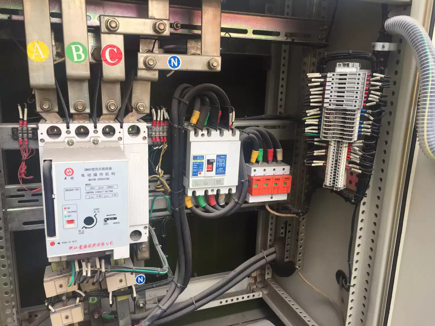
Figure 12: Thor SPD installed in distribution board with short lead lengths and upstream MCCB protection
Frequently Asked Questions
What’s the difference between 4+0 and 3+1 wiring in a three-phase SPD?
4+0 connects L1, L2, L3, and N directly to PE — standard for TN-S systems where N-PE voltage is close to zero. 3+1 protects phases relative to neutral with a separate N-PE path — required for TT systems where N-PE voltage at the board is not zero. Wrong mode = premature MOV failure.
Does an SPD need its own circuit breaker?
Yes. Every SPD requires an upstream OCPD to disconnect it in case of short-circuit failure. Without one, a failed SPD creates a permanent fault current path. The backup fuse rating must match the SPD’s short-circuit current rating — check the datasheet.
Does SPD wiring differ between TN-S and TT earthing systems?
Yes. TN-S uses 4+0 or 2+0 because N-PE voltage is near zero. TT systems have a voltage difference between neutral and local earth — a 4+0 SPD will conduct continuously on the N-PE path. TT requires 3+1 mode with a separately rated N-PE MOV.
How do I know if my SPD is wired correctly?
Check three things: visual fault indicator (green = OK, red = end of life), lead lengths within 0.5m total, and connection mode matches the earthing system. If the SPD has remote signalling contacts, connect them to a monitoring system for automatic fault detection.
Protect Your Installation with the Right SPD
Wiring an SPD correctly starts with the system it’s going into — the earthing arrangement, voltage level, and protection type required. Thor Electric SPDs cover the full range of AC, DC, and PV applications, certified to IEC, TUV, CE, RoHS, CB and ISO standards, with pluggable modules for field replacement without rewiring.
For product selection support or project-specific recommendations, contact the Thor Electric Team.