Surge Protective Devices (SPD) is a critical safety component that protects valuable electronics from transient overvoltages by diverting damaging surge currents. SPDs sustain irreversible accumulated weariness under each surge event and has a finite operational lifespan.
It is anticipated that all SPD devices will age as a result of their function (as shown in Figure 1). Consequently, it is normal for an SPD to reach the end-of-life and require module change. International standards such as IEC 61643-11 mandates that the device must safely disconnect itself to prevent fire or short-circuit risks.
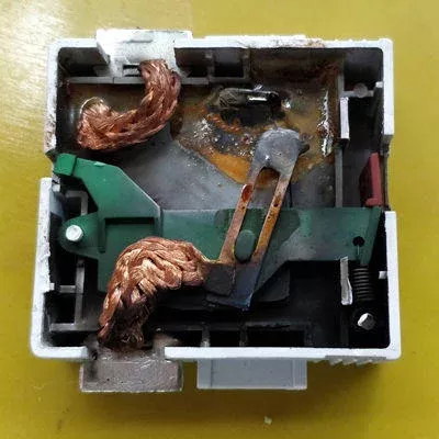
Figure 1 – Internal View of a Failed SPD Module
The process of SPD aging and component degradation
The Metal Oxide Varistor (MOV) is the primary element for surge dissipation in the immense majority of modern SPDs. An MOV is a type of semiconductor device that has an extremely nonlinear voltage-current characteristic, making its electrical resistance varied dramatically according to the applied voltage.
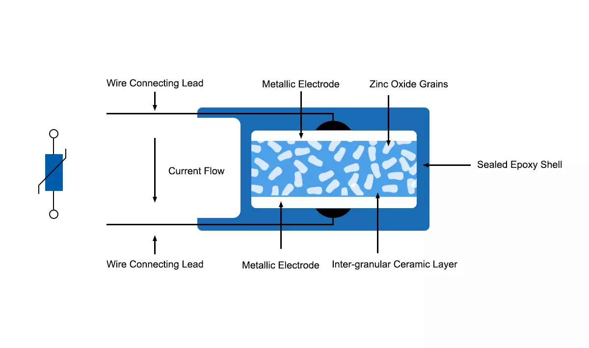
Figure 2 – MOV internal construction
In normal system operation, while the voltage is constant, the MOV has a very high resistance and is essentially transparent to the circuit, causing only a very small leakage current. However, in the case of a transient overvoltage, if the voltage between the MOV terminals is higher than its designated activation voltage called the Maximum Continuous Operating Voltage (MCOV), the MOV’s resistance then lowers considerably and instantaneously, by several orders of magnitude.
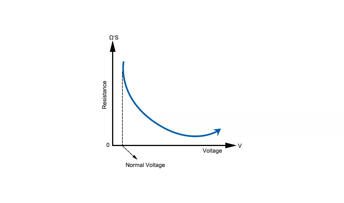
Figure 3 – MOV static resistance curve
The rapid change transforms the MOV into a highly conductive path, creating a low-impedance channel for the excess surge current to be safely diverted to the electrical grounding system, away from the protected equipment.
The protective action, while fundamental to the SPD’s function, is not without consequence for the MOV itself. Each time an MOV conducts a significant surge current, its internal zinc oxide grain microstructure experiences intense thermal and electrical stress.
As time progresses, the cumulative and irreversible decline of the component results from the repetitive stress. Even minimal, yet cyclic surges are expected in a facility, from equipment, such as starting and stopping large motors, contribute to the aging process. The decline is generally characterized by a downward trend in the MOV activation voltage and, more importantly, an upward trend in measurable leakage current under normal standby conditions.
As the MOV continues to age and leakage current increases, it will dissipate more power as heat during normal operation. Given that MOVs have a negative temperature coefficient, the initial heating lowers the device’s internal resistance further, thereby allowing even more leakage current to flow through the MOV and produce even more heat. This will repeat, thus creating a dangerous positive feedback loop known as thermal runaway. During thermal runaway, the MOV temperature rises uncontrollably and rapidly. If thermal runaway proceeds, the MOV will eventually experience catastrophic failure and potentially cause smoke, outgassing, ignition, or explosion fragmenting the component.
Transient surges, lasting for only microseconds, are different from temporary overvoltages (TOVs), which are a form of sustained overvoltage that can last from milliseconds to seconds or even longer. Multiple surge protective devices (SPDs) are designed to dissipate short duration events, but in most cases they are not capable of dissipating the thermal energy from a sustained TOV event. Furthermore, when subjected to a temporary ovevoltage (TOV), MOVs can rapidly accelerate degradation and move immediately into thermal runaway of the MOV, thus reducing the actual service life of the SPD.
Thus, the actual service life of an SPD is entirely reliant on the electrical environment, which includes the frequency, duration and magnitude of transient surges and temporary overvoltages that will age each of the components that comprise the operational limits of the SPD protective device.
Thermal disconnector and end-of-life operation
To prevent the hazardous thermal runaway condition in a degrading Metal Oxide Varistor (MOV), SPDs are required by international and national standards to fail safely. The governing safety standard, IEC 61643-11 mandates that all SPDs must incorporate a specifically designed internal disconnector. Often referred to as a thermal disconnector, the internal disconnector is the most critical element for ensuring the safe end-of-life performance of the device.
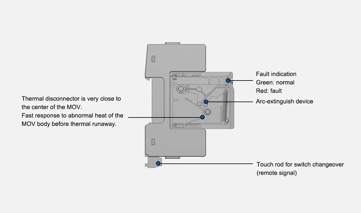
Figure 4 – Internal construction of an MOV based SPD
The thermal disconnector is designed to continuously monitor the thermal state of the MOV. It is typically a thermally sensitive element, such as a specialized solder joint or a spring-loaded mechanical latch, placed in direct physical contact with the MOV body.
When an aging MOV begins to enter thermal runaway, its temperature rises rapidly. The thermal disconnector activates at a predetermined temperature, a point reached well before the MOV can overheat to the point of catastrophic failure. Upon activation, the disconnector’s primary and sole function is to physically and permanently isolate the degraded MOV from the electrical circuit.
The successful operation of the internal disconnector is what constitutes the safe end-of-life of the SPD. The “failure” a user observes is, in fact, the final, successful execution of a mandated safety feature that has prevented a much more dangerous situation. It also prevents the SPD from failing into a low-impedance short-circuit state, which could otherwise trip an upstream circuit breaker and cause a disruptive power outage to the entire circuit.
The function of the SPD status indicator
A critical safety event like an internal MOV disconnection requires a clear communication method for maintenance personnel. International standards IEC 61643-11 mandate that SPDs must provide an visual indication of their operational state.
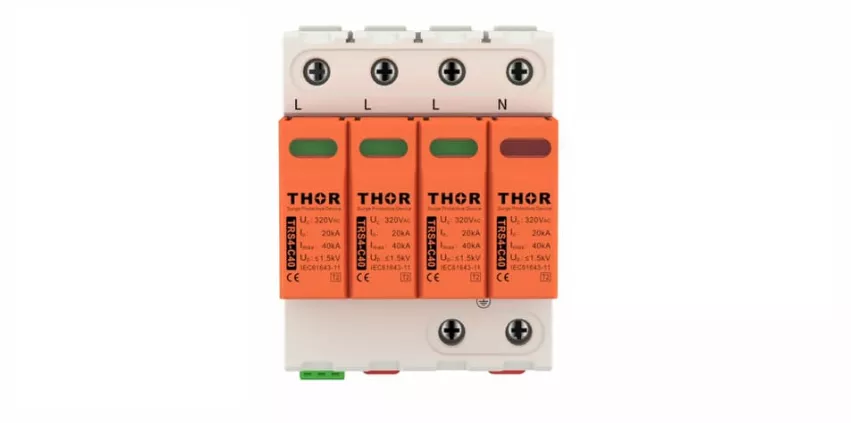
Figure 5 – Status indicator
An SPD status indicator is a required feature, serving as a primary communication link to the outside world. Most common implementations use a mechanical flag indicator integrated directly with the thermal disconnector mechanism. A healthy, operational state displays a specific color, typically green. When the thermal disconnector activates to isolate an end-of-life MOV, its mechanical action simultaneously releases the indicator flag, causing a visible color change to red.
Such a change provides immediate, at-a-glance confirmation that the SPD module has reached its end-of-life and is no longer providing protection. It serves as a direct and actionable signal for proactive maintenance. For supporting facility management in complex or remote installations, many SPDs also incorporate auxiliary electrical contacts, often called remote signaling contacts.
Mechanically linked to the disconnector, the contacts change their electrical state when the SPD reaches its end-of-life. Electronic monitoring of an SPD’s status is made possible by this feature, allowing integration with a Building Management System (BMS), a SCADA system, or a simple alarm panel.
Remote indication capability proves crucial for unmanned sites or large facilities with hundreds of SPDs, as it enables centralized monitoring and immediate dispatch of maintenance personnel. A status indicator, whether local or remote, transforms an SPD from a passive component into an active part of a managed electrical system, signaling precisely when and where intervention is required.