The choice between 4+0 and 3+1 configuration in a three-phase SPD is not a preference — it is determined by your grounding system. Installing a 4+0 SPD in a TN-C system will expose the N-PE varistor to sustained overvoltage and burn it out. Installing a 3+1 SPD where it is not needed adds cost without benefit. The two configurations protect against different surge paths and are not interchangeable.
What do 4+0 and 3+1 mean in 3-Phase SPDs
When selecting a surge protective device for a three-phase system, the terms “4+0” and “3+1” refer to the internal circuit configuration. They define how the protective components are connected between the live conductors (L1, L2, L3, N) and the Protective Earth (PE).
What is 4+0 configuration?
The 4+0 configuration uses a parallel protection mode where all live conductors are protected directly to the Protective Earth. Under this arrangement, four identical metal oxide varistor (MOV) protective devices are linked across L1-PE, L2-PE, L3-PE, and N-PE.
L1 -> PE
L2 -> PE
L3 -> PE
N -> PE
Figure 1 – 4+0 configuration SPD internal structure
What is 3+1 configuration?
However, the 3+1 approach splits the protection mechanism into a pair of stages.First, the three phase lines (L1, L2, L3) are protected against the Neutral conductor, handling differential mode surges. Second, and most critically, a separate and dedicated protective component, typically a high-capacity Gas Discharge Tube (GDT), provides protection between the Neutral and Protective Earth.
L1 -> N
L2 -> N
L3 -> N
N -> PE
Figure 2 – 3+1 configuration SPD internal structure
Common mode and differentiating mode protection
Common mode protection
Common mode overvoltages are transients that affect all live conductors simultaneously. For example, during a direct lightning strike or a major short-circuit event—all live wires (L1, L2, L3, and N) rise in potential together relative to earth. In this situation, there’s little or no voltage difference between the conductors themselves, but all of them are elevated above the Protective Earth (PE). Therefore, the goal of common mode protection is to provide a safe, parallel path to divert the shared surge energy from all four wires directly to the ground.
In a 4+0 configuration, surge protection is achieved by connecting all four live conductors in parallel directly to the Protective Earth (PE). There is a separate and typically identical protective module, usually a Metal Oxide Varistor (MOV), for each path: L1-PE, L2-PE, L3-PE, and N-PE, providing four direct pathways for transient energy to be safely discharged to the ground.
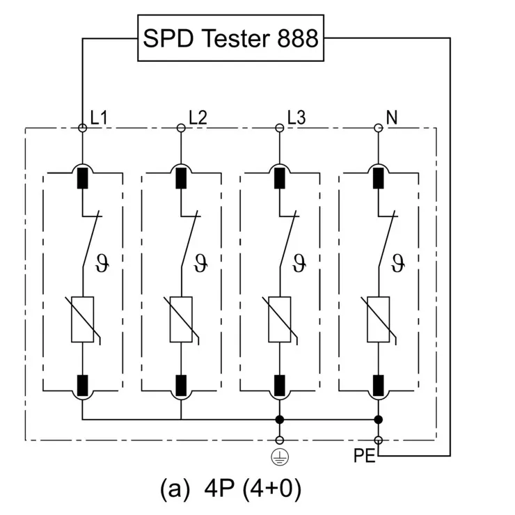
Figure 3 – Common mode surge protection diagram
Differentiating mode protection
Differential mode overvoltages, on the other hand, are typically generated within a facility. Sources like the switching of large inductive loads (motors, transformers) or the operation of variable frequency drives can cause a transient voltage spike on one or two specific conductors. There will be a huge potential difference within the electrical circuit itself, most commonly between a line and neutral (L-N) or between two lines (L-L). It works by creating a direct, low-impedance path specifically between the affected conductors (e.g., from Line to Neutral).
The 3+1 configuration employs a two-stage protection strategy. In this mode, surge protection is first achieved by providing direct paths between the three phase conductors (L1, L2, L3) and the neutral conductor. As shown in Figure 4, each phase line is connected to the neutral via a protective module containing a varistor (MOV) and a thermal disconnector.
Subsequently, the potential difference will be cleared off via N-PE path. The neutral conductor is connected to the Protective Earth (PE) through a specific, high-capacity component, identified in the diagram by the circular symbol for a Gas Discharge Tube (GDT).
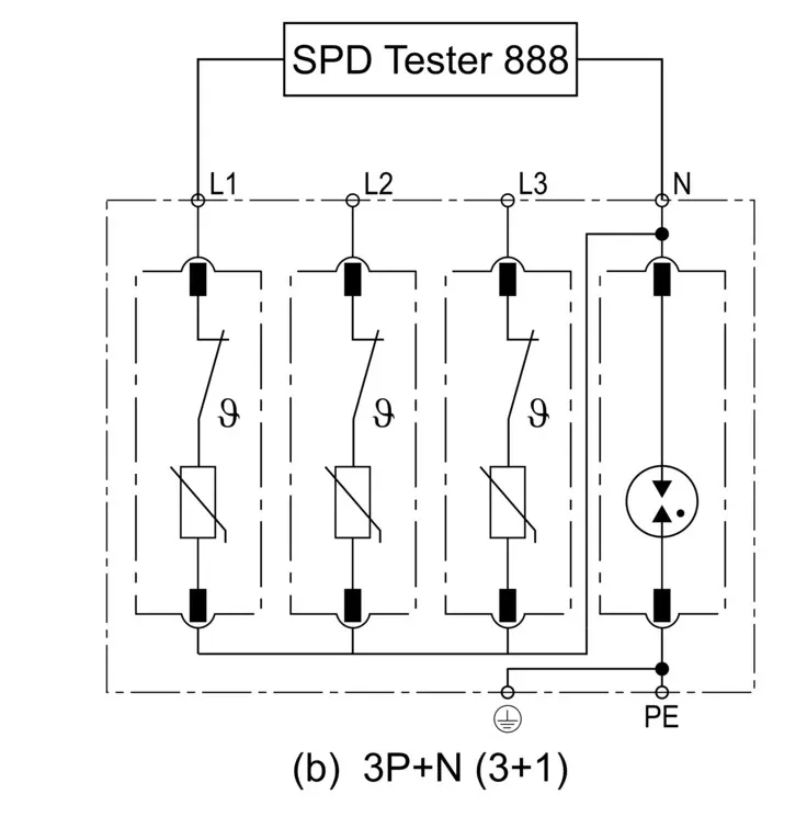
Figure 4 – Differentiating mode surge protection diagram
How to choose the right SPD mode for your 3 Phase systems
Selecting the right SPD configuration for three-phase surge protection requires a systematic evaluation of the expected protection performance, the type of earthing system in use, and any additional SPD functions.
Grounding system
The grounding system of your electrical installation is, without any doubt, the most important factor when selecting the right SPD protection mode. Ignoring this factor may cause unnecessary protection compromises, leading to premature SPD failure, or even create a critical safety hazard. The two most common configurations, 4+0 and 3+1, have specific applications based on different conditions.
TN-S System
Both 4+0 and 3+1 configurations can satisfy TN-S system surge protection requirements, as long as the rated In and Up values are compatible with your system. In a TN-S system, as shown in Figure 5, the Neutral and Protective Earth conductors are bonded together at the source transformer but run as separate conductors throughout the installation.
Because they share the same earth reference point, there is practically no voltage potential between them under normal operating conditions, making the MOV connected between N and PE in a 4+0 SPD configuration remain unstressed during normal operation, as no continuous current or voltage difference exists across it.For TN-S installations, THOR’s Type 2 AC Surge Protection Devices are available in both 4+0 and 3+1 configurations to suit your project specification.
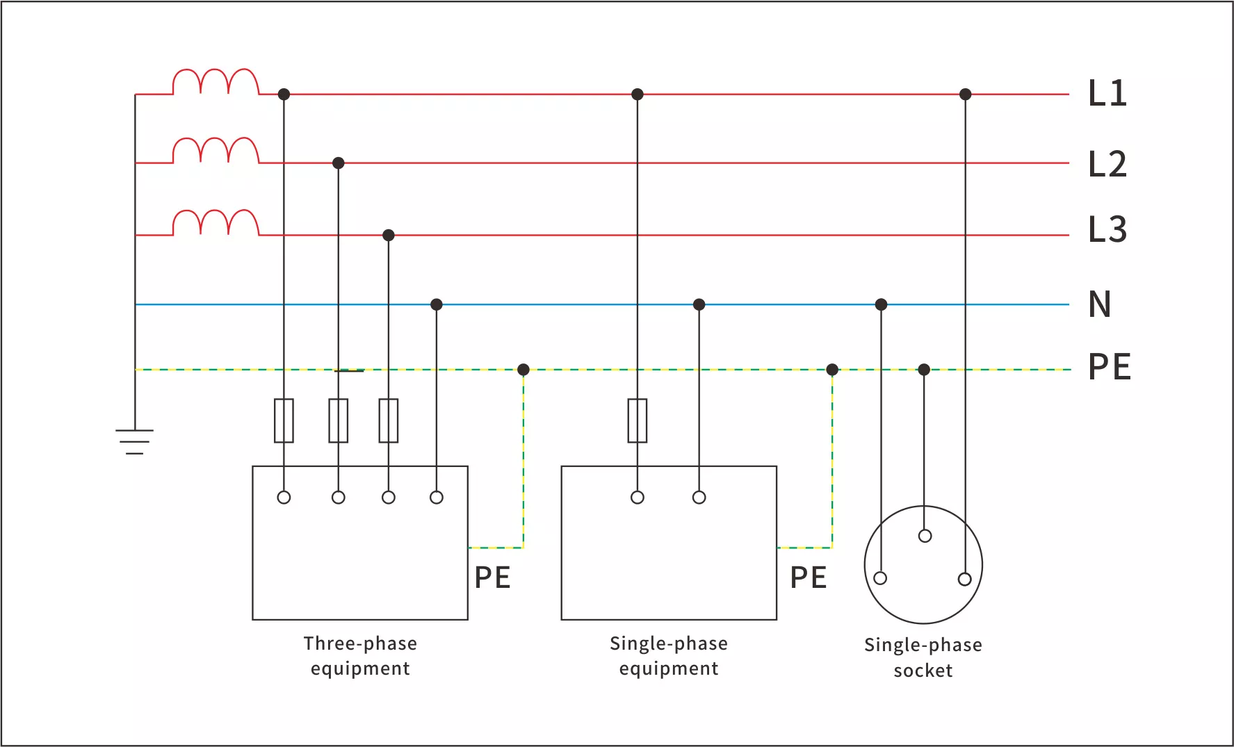
Figure 5 – TN-S grounding system
TT System
For a TT system, it is mandatory to choose the 3+1 configuration SPD. It is not simply because it’s better in protection effect, but because it is the only safe option.
Within a TT system, as shown in Figure 6, the neutral and PE are separated at the source; the installation has its own independent earth electrode, which may cause significant and fluctuating potential difference between the Neutral and PE conductors, especially under fault conditions.
If a 4+0 SPD were used, its N-PE MOV would be subjected to the continuous voltage, leading to its rapid degradation and eventual short-circuit failure.
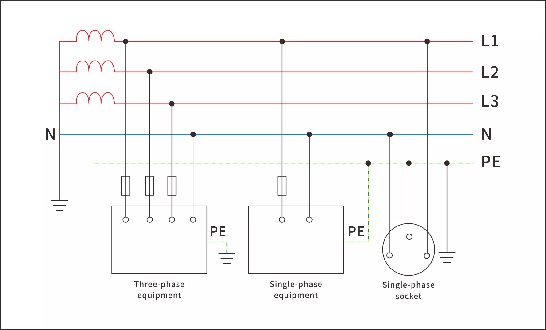
Figure 6 – TT grounding system
The 3+1 configuration meets the requriement with addtional Gas Discharge Tube unit. Unlike an MOV, the GDT remains completely non-conductive under normal operating voltages, regardless of small potential differences between Neutral and Earth.
When a surge occurs, the GDT activates instantaneously and create a low-impedance path that safely equalizes the potential between N and PE to discharging the transient energy to earth. Once the surge has passed, it automatically returns to its insulating state.THOR’s Type 1+2 AC SPDs are designed with the 3+1 configuration as standard, making them fully compliant and safe for TT system installations.
Overall protection effect
If you require better overall protection, the 3+1 configuration almost always excels. This is because it is specifically designed to provide protection against both common mode (L/N-PE) and differential mode (L-N) surges. The direct L-N connections offer a superior, low-impedance path to clamp internally generated differential mode surges, which are a common threat to sensitive electronics.
The 4+0 configuration, while effective for common mode surges, addresses differential mode surges indirectly and less effectively, as the surge must traverse two separate components (L-PE and N-PE), potentially resulting in a higher let-through voltage to the equipment.
Sensitivity of the Equipment
The nature of the load you are protecting is a critical consideration. For most of the equipment such as distribution panels, lighting circuits, or heating elements, a 4+0 SPD may be deemed as sufficient. However, for protecting sensitive, high-value, or critical electronics—such as PLCs, servers, IT infrastructure, and medical equipment—the 3+1 configuration is strongly recommended as it offers a more precise and lower clamping voltage exactly where these devices are most vulnerable.
Cost efficiency
Budget has been a important factor in any project upon decision making. Generally, the 4+0 configuration tends to be slightly more cost-effective because it is made of four identical, mass-produced MOV modules. The 3+1 configuration may cost slightly higher initial at the beginning, primarily due to the specially designed Gas Discharge Tube.
However, when looking at cost efficiency, it’s important to think beyond just the initial price — what really matters is the total cost of ownership. Despite that a 3+1 SPD may cost a bit more at the beginning, the differentiating mode it offers with better durability and performance often maks it the more economical choice in the long run.Compare THOR’s full range of three-phase AC surge protection devices — including both 4+0 and 3+1 configurations — to find the right fit for your project budget and system requirements.
Conclusion
From what we have discussed, although 4+0 and 3+1 SPD Configuration both provide surge protection for 3 phase systems, they are distinct in working mechanism and performance. 4+0 configuration offers common mode surge protection while 3+1 configuration offers differentiating mode protection.
It’s important to assess running grounding system, the degree of equipment sensitivity, protection effect when choosing the correct type configuration of 3-Phase surge protection device. Overall, the 3+1 configuration is more recommended if you are open to a higher initial cost.