A metal oxide varistor is a voltage-dependent resistor at the heart of most surge protective devices. Under normal voltage it sits at high impedance — microamperes of leakage, nothing more. When a surge hits, it switches to a low-impedance path in under 25 nanoseconds, diverting surge energy to earth and clamping the voltage before it reaches your equipment. Once the transient passes, it returns to standby. Choose the right MOV for your installation and it protects for years. Underspec it or wire it wrong, and the protection is gone — even if the SPD looks fine from the outside.

What Is a Metal Oxide Varistor?
A metal oxide varistor (MOV) is a nonlinear resistor made from sintered zinc oxide (ZnO) grains mixed with small amounts of bismuth, cobalt, and other metal oxides. The grain boundaries form a network of semiconductor junctions — essentially back-to-back diodes — that block current at normal voltage and conduct heavily the instant voltage exceeds the varistor threshold. Under IEC 61643-11, it is the standard energy-handling component in Type 1, Type 2, and Type 1+2 SPDs.
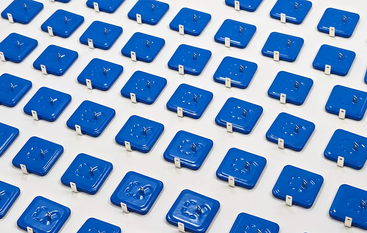
The structure is what gives a metal oxide varistor its defining characteristic: a sharp knee in the voltage-current curve. Below the varistor voltage (V₁mA), impedance sits in the megaohm range. Above it, impedance collapses and it conducts surge current to earth. This nonlinearity is the whole game — a linear resistor would either block everything or conduct constantly. Neither protects anything.
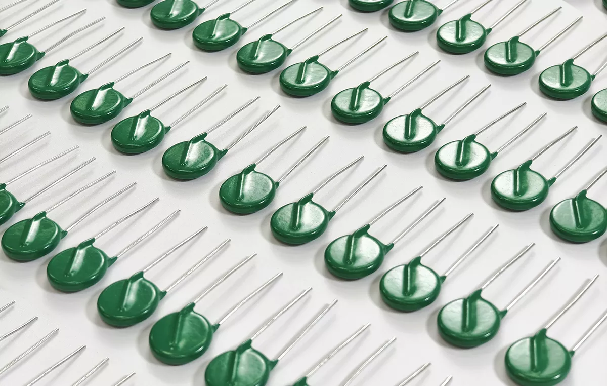
MOVs are not one-size-fits-all. The varistor voltage, energy rating, and disc diameter all change depending on system voltage and expected surge exposure. A 275 V AC SPD uses a different varistor disc than a 1000 V DC PV combiner box SPD. The underlying ZnO grain-boundary mechanism is the same.
How an MOV Responds to a Surge
In standby, the varistor draws microamperes — functionally invisible to the circuit. When a transient arrives — whether a lightning-induced 8/20 µs pulse or a switching transient from a nearby capacitor bank — the voltage across its terminals rises past V₁mA. The grain-boundary junctions break down. It becomes a conductor.
Surge current takes the lowest-impedance path: through the varistor to earth, not through the equipment it protects. The voltage your load sees during this event is the clamping voltage (Vc), also called the voltage protection level (Up) in the context of a complete SPD. For a properly specified Type 2 SPD, Up sits at 1.5 kV or below — comfortably under the 2.5 kV impulse withstand of Category II equipment defined in IEC 60664-1.
After the surge passes, it returns to high impedance. No reset. No fuse replacement. For minor surges — the kind that happen routinely on a distribution network with switching loads — it does this indefinitely. For major surges near the energy rating, each event consumes part of its service life. More on that in the limitations section below.
Table 1 — Key MOV Electrical Parameters
| Parameter | What It Means |
| Varistor Voltage (V₁mA) | The DC voltage at which 1 mA flows through the MOV. Defines the knee point where the device transitions from blocking to conducting. |
| Maximum Surge Current (In / Imax) | In is the repeatable peak surge current (8/20 µs) the MOV handles 15 times without damage. Imax is the single-event absolute maximum. |
| Clamping Voltage (Vc / Up) | The residual voltage across the MOV during a rated surge event — the voltage that reaches the protected equipment. Must sit below the impulse withstand of the load. |
| Energy Absorption (J) | Single-pulse energy the MOV dissipates without failure. A higher joule rating means more endurance, but joule ratings are not directly comparable across manufacturers without the same test waveform. |
| Response Time | Under 25 ns for a standard MOV — faster than GDTs and fast enough for all standard surge waveforms including the 1.2/50 µs voltage impulse and 8/20 µs current impulse. |
| Leakage Current | The steady-state current through the MOV at nominal operating voltage. Typically microamperes when new. A rise over time indicates degradation. |
| Nonlinear Coefficient (α) | How sharply the MOV transitions from blocking to conducting. Higher α means tighter clamping. ZnO MOVs achieve α values above 30 — far steeper than silicon carbide varistors. |
Where MOVs Are Used
MOVs sit wherever a surge path exists and a load is worth protecting.
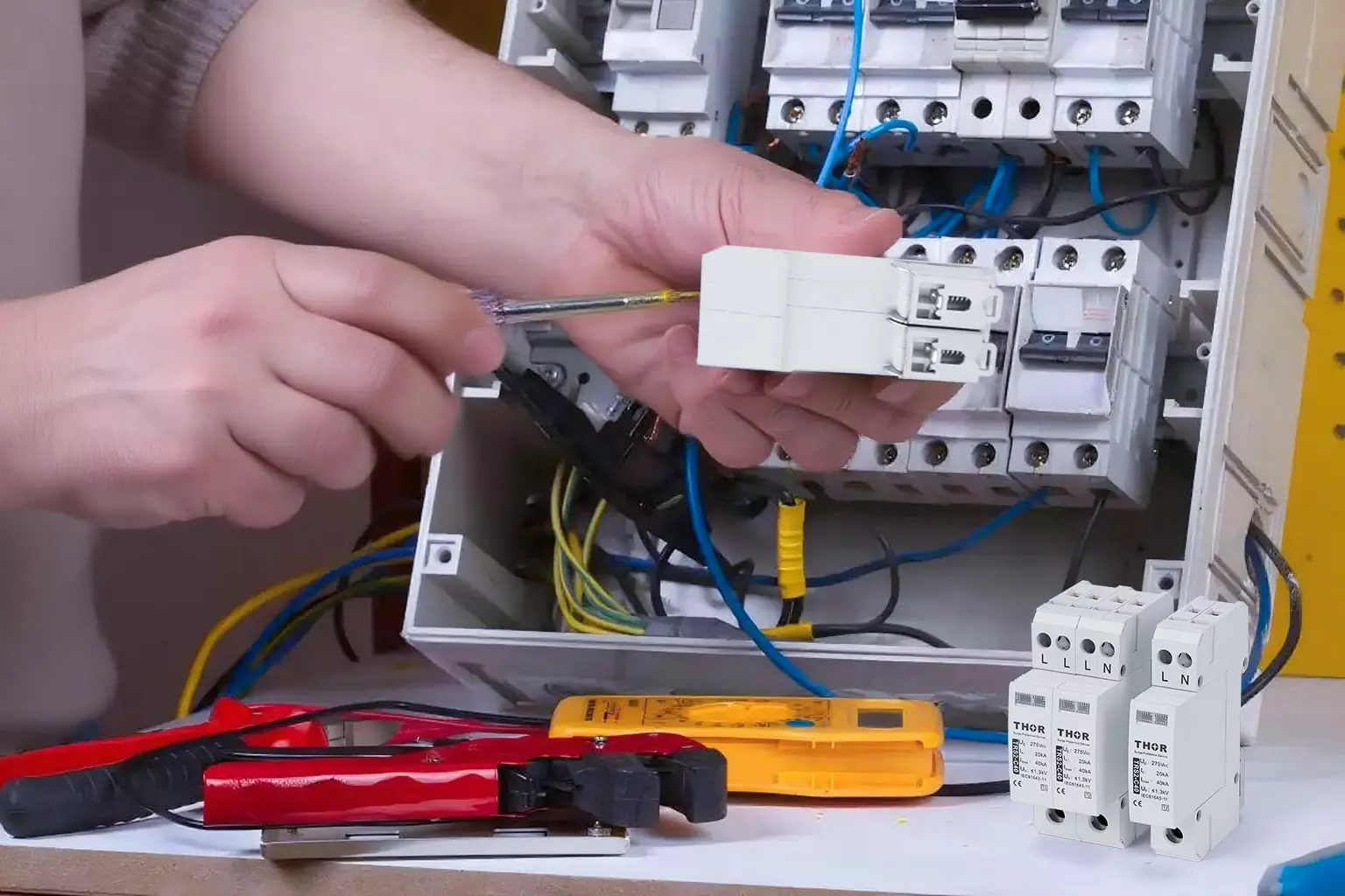
AC power distribution. Varistors are the core of Type 2 SPDs at sub-distribution boards, clamping switching transients and induced lightning surges — the everyday threats that wear down equipment insulation over time. Paired with a gas discharge tube (GDT) or spark gap upstream in a Type 1+2 configuration, they cover direct and indirect surge exposure from a single enclosure.
DC and PV systems. Varistors rated for DC voltage — look for the Ucpv parameter instead of Uc — sit at the inverter DC input and the combiner box output. The selection rules are the same as AC: Ucpv must exceed maximum string voltage under all temperature conditions. But DC SPDs are tested to IEC 61643-31, not IEC 61643-11, because DC arcs do not self-extinguish at zero crossing the way AC arcs do. MOVs are the defining component in voltage limiting SPDs, the most widely deployed protection type in low-voltage installations.
Telecom and signal lines. Low-capacitance varistors protect Ethernet, RS485, and coaxial circuits. Parasitic capacitance matters here — a standard power-line varistor with nanofarads of capacitance degrades a high-frequency signal. Low-capacitance variants (under 10 pF) keep insertion loss within acceptable limits.
Consumer equipment. Routers, IP cameras, set-top boxes — small varistor discs or chip varistors sit across the power input inside the device or power strip. When the LED goes out on that surge protector strip, a varistor sacrificed itself.
MOV Limitations and Failure Modes
MOVs are not flawless. Four failure modes matter at the specification stage.
Aging and leakage current drift.
Every surge ages the device. Leakage current creeps up. Varistor voltage drifts. End of life is not measured in calendar years — a metal oxide varistor in a quiet suburban panel may last a decade; one in a factory with large motor loads switching daily may need replacement in three years. A simple field test: measure leakage current at operating voltage. If it has doubled from the commissioning baseline, schedule replacement.
Thermal runaway.
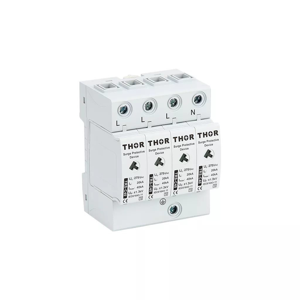
When a metal oxide varistor faces sustained overvoltage — a TOV condition from a neutral fault, for example — it does not clamp the way it does for a microsecond transient. It conducts continuously, heats up, and if not disconnected, enters thermal runaway: more heat lowers resistance, lower resistance draws more current, more current produces more heat. The fix is a thermal disconnect built into the SPD — a solder joint that melts and physically separates the varistor from the circuit before fire temperature is reached. Thor’s TRS series ties this to a colour-coded indicator window: green means operational, red means replace.
Residual voltage mismatch.
The clamping voltage a Type 2 SPD delivers — nominally 1.5 kV — protects most industrial equipment but may not protect sensitive electronics with lower impulse withstand. The answer is multi-stage protection covered in the three-level defence table: a GDT or spark gap at the service entrance for bulk energy, a varistor at the sub-board for the main clamp, and a TVS diode at the equipment for final precision clamping under 50 V. Each stage catches what the previous stage could not.
Short-circuit failure mode.
MOVs fail short, not open. A failed varistor still in circuit draws continuous current and can overheat the board or enclosure. IEC 61643-11 requires an overcurrent protective device in series with every SPD — not to protect the load from surges, but to disconnect the SPD safely when the varistor eventually fails.
Table 2 — Varistor Failure Modes and Mitigations
| Failure Mode | Root Cause | Mitigation |
| Aging and voltage drift | Repeated surge stress, thermal cycling | Periodic leakage current testing; replace at 2× baseline leakage |
| Thermal runaway and fire | Sustained TOV exposure, neutral fault | Integrated thermal disconnect with visual indicator |
| Parasitic capacitance | Intrinsic MOV grain structure | Low-capacitance MOV variant (<10 pF) or TVS diode for RF/data lines |
| Short-circuit at end of life | MOV degradation; all MOVs fail short | Series OCPD (fuse or MCB) per IEC 61643-11 requirement |
Table 3 — Three-Level Surge Protection Architecture
| Level | Location | Components | What It Does |
| 1 | Service entrance / outside building | Lightning rod, down conductor, grounding system | Redirects direct lightning strikes to earth |
| 2 | Main distribution board | Type 1 or Type 2 SPD (MOV + GDT) | Clamps incoming conducted and induced surges |
| 3 | Equipment / terminal | TVS diode, filter, compact MOV-based SPD | Final precision clamping for sensitive electronics |
Table 4 — Varistor vs GDT vs TVS Diode
| Component | Response Time | Energy Handling | Clamping Precision | Best Use |
| MOV | <25 ns | Moderate–High | Moderate | General-purpose AC/DC surge suppression |
| TVS Diode | <1 ns | Low–Moderate | High | Sensitive electronics, data lines, final stage |
| GDT | ~100 ns–µs | Very High | Low | Primary lightning diversion, Type 1 SPD front end |
FAQ
What is a metal oxide varistor?
A metal oxide varistor (MOV) is a voltage-dependent nonlinear resistor made from sintered zinc oxide grains with small amounts of bismuth, cobalt, and other metal oxides. Under normal voltage it blocks current — impedance is in the megaohm range. When voltage exceeds its varistor threshold, impedance collapses in under 25 ns and it diverts surge current to earth. It is the standard energy-handling component inside most AC and DC surge protective devices.
How does an MOV differ from a GDT or TVS diode?
The three components occupy different points on the speed-versus-energy tradeoff. GDTs absorb the highest surge energy (direct lightning) but respond slowly — around 100 ns to microseconds. MOVs respond in under 25 ns with moderate-to-high energy capacity, making them the general-purpose choice. TVS diodes respond in under 1 ns with precise clamping but low energy tolerance, suited for the final protection stage at sensitive equipment. See Table 4 above for a side-by-side comparison.
What causes an MOV to fail?
Three things. Repeated surge stress near the energy rating gradually degrades the ZnO grain structure, raising leakage current until the device drifts out of spec. Sustained overvoltage (TOV) forces it into continuous conduction, causing thermal runaway — the leading cause of catastrophic failure. And manufacturing defects in substandard varistors — inconsistent grain size, incomplete sintering — can cause premature failure even under normal conditions. A quality varistor tested to IEC 61643-11 has passed thermal runaway and endurance testing before it reaches your panel.
How do I know if the varistor inside my SPD is still working?
Check the SPD’s visual indicator first — Thor’s TRS series uses a colour-coded window: green means the varistor is operational, red means end of life and the cartridge needs replacement. For installations without visual indicators, measure leakage current at the SPD earth connection with a clamp meter. A doubling from the commissioning baseline means it is degrading and should be replaced. Without a baseline, anything above 1 mA at nominal voltage warrants investigation.
Can I replace just the varistor, or the whole SPD?
If your SPD uses modular cartridges — as Thor’s TRS series does — you replace the varistor cartridge without rewiring or removing the base. The indicator window shows which cartridge needs swapping. For sealed SPD units where the varistor is soldered or potted inside the enclosure, the entire SPD must be replaced. Modular design saves material cost and downtime in installations with multiple protection points.
Are varistors used in DC surge protection for solar and battery systems?
Yes, but the device must be rated for DC. An AC-rated varistor used on a DC circuit may fail to interrupt follow current after a surge because DC arcs do not self-extinguish at zero crossing. DC SPDs carry the Ucpv parameter instead of Uc and are tested to IEC 61643-31. Thor’s TRS3-C40 covers DC system voltages from 600 V to 1800 V for PV combiner boxes, inverter DC inputs, and battery storage systems.
Thor Electric AC and DC Surge Protective Devices
Thor Electric manufactures Type 1, Type 2, and Type 1+2 AC SPDs with varistor-based protection certified to IEC 61643-11, plus DC SPDs certified to IEC 61643-31 for PV and battery systems. The TRS series uses modular varistor cartridges with visual end-of-life indicators — replace the cartridge, not the whole SPD. Samples, custom Uc and Ucpv variants, and OEM configurations are available.
All Thor Electric SPDs are certified to IEC, TUV, CE, RoHS, CB and ISO standards. Certificates can be verified at TUV Rheinland Certipedia.
Contact the Thor Electric team for project-specific requirements: https://spds.global/contact-us/