
An IT earthing system keeps the supply source isolated from earth, or connects it through a deliberately high impedance, while every exposed metal part of the installation is earthed through a local electrode. A first earth fault therefore draws only a small current, and a correctly designed installation keeps running while a monitoring device, usually an insulation monitoring device, raises the alarm. A second fault on a different conductor must trip.
That continuity has a price that most explanations leave out. During a first fault, the two healthy phases sit at full line-to-line voltage to earth, sometimes for days. Every device connected between a line and earth, including the surge protective device, has to be rated for it: on a 230/400 V IT earthing system, the SPD’s line-to-PE modes need a Uc of at least 440 V.
What is an IT earthing system?
An IT earthing system is a low-voltage arrangement in which no live conductor is directly connected to earth at the source, and the exposed-conductive-parts of the installation are earthed through the installation’s own electrode. The first letter, I, stands for isolated: the transformer star point is either floating or earthed through an impedance of a kilohm or more. The second letter, T, comes from the French terre and means the equipment frames go to a local earth.
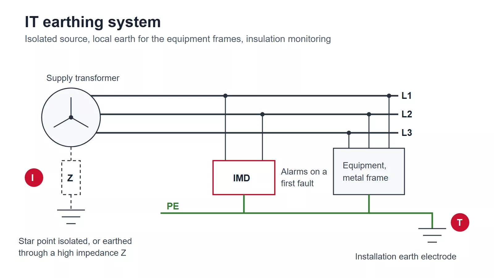
Figure 1 — IT earthing system: an isolated or impedance-earthed source, an insulation monitoring device, and equipment frames earthed through the installation electrode.
Compared with TN and TT, the arrangement is more work to design and maintain. People accept that work for one reason: a single insulation fault can stay on the system while the plant keeps running.
How an IT earthing system behaves on a first fault
In a TN system, a line-to-frame fault is a short circuit back to the earthed star point, and the protective device has to clear it in a fraction of a second. In an IT system there is no low-impedance route back to the source. The fault current has to return through whatever connects the network to earth: the source impedance, if one is fitted, and the leakage capacitance of every cable and filter on the system.
That current is small. Take a 230/400 V three-wire network whose cables add up to about 1 µF per phase to earth. A first fault on L1 draws roughly 0.2 A through the earth, and across a 50 Ω installation electrode that produces a touch voltage of about 11 V. IEC 60364-4-41 sets the condition for leaving the fault in place: the electrode resistance multiplied by the first-fault current must not exceed 50 V a.c. Larger networks with long cable runs and many drive filters can push the first-fault current into amps, so the calculation belongs to each installation rather than to a rule of thumb.
The part that matters for equipment selection is what happens to the voltages. Before the fault, each phase sits about 230 V from earth. Once L1 is solidly faulted to earth, L1 is at earth potential, and L2 and L3 move to 400 V from earth, the full line-to-line voltage. In a correctly designed system nothing disconnects, so the installation runs in that state until someone finds and repairs the fault.
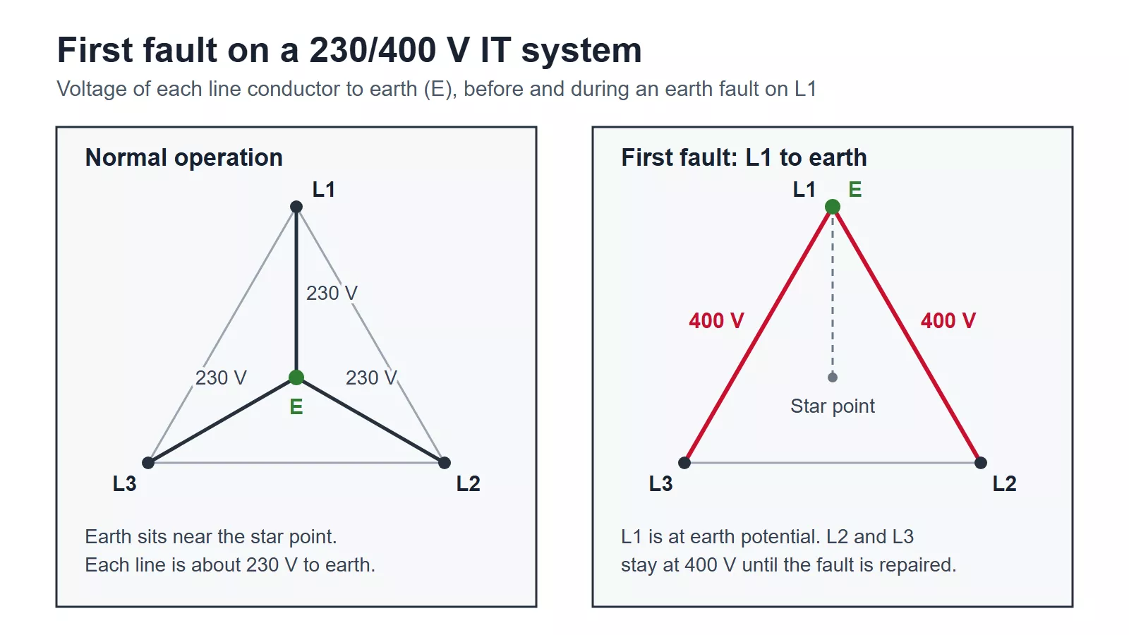
Figure 2 — Phase-to-earth voltages on a 230/400 V IT system before and during a first fault on L1.
Because the design leaves the first fault connected, something else has to report it. IEC 60364-4-41 requires a monitoring device that gives a sustained audible or visual alarm when a first fault occurs. The usual choice is an insulation monitoring device (IMD) built to IEC 61557-8, which measures the insulation resistance between the live conductors and earth continuously and alarms when it falls below the set threshold. A residual current monitor (RCM) is also permitted where the residual current is large enough to detect, and Group 2 medical IT systems use an IMD with additional requirements under IEC 60364-7-710. Neither device disconnects anything. Their job is to make sure the first fault gets located and repaired before a second one turns it into a short circuit, and a site that ignores the alarm has lost the main protection the arrangement relies on.
Second fault: when an IT earthing system must trip
A second fault on a different live conductor closes a loop between two conductors through the protective conductors or the earth. Depending on which conductors are involved, that is a line-to-line fault or, where the neutral is distributed, a line-to-neutral fault. Either way the installation has to disconnect automatically, and how it does so depends on how the equipment frames are earthed.
| Situation | What happens | Device that acts |
| First fault, any arrangement | Small current through the earth and network capacitance; supply continues when the protection is coordinated | IMD or RCM alarms. An RCD set too sensitively may trip |
| Second fault, all frames bonded to one common PE | Fault current flows through the PE conductors with no electrode in the loop; behaves like a TN fault | Overcurrent device (fuse or circuit breaker), sized with TN-style loop impedance calculations |
| Second fault, frames earthed in separate groups or individually | Fault current passes through two electrodes and the ground between them; too low for reliable overcurrent tripping | RCD on each separately earthed group or item, following TT rules |
The common-PE case is the normal design. Engineers calculating it conventionally double the circuit loop impedance, because the two faults can sit at opposite ends of the installation. With a distributed neutral, the lowest fault current occurs when one of the faults is on the neutral, so the calculation uses the phase-to-neutral voltage.
The separately earthed case is where RCDs become mandatory. The logic is the same as in a TT earthing system: two electrodes in series limit the current, so a residual current device has to detect the fault instead of an overcurrent device.
RCDs also interact with the first fault, which is easy to get wrong. The first-fault current returns through earth and the network capacitance, so any RCD it passes through sees it as residual current. A sensitive RCD can trip on a first fault and throw away the continuity that justified an IT system in the first place. Where RCDs are used, their rated residual operating current has to sit above the first-fault current expected on that part of the network, and the leakage capacitance has to be estimated before the rating is chosen. That is also why first-fault monitoring falls to an IMD or RCM, which alarm, while RCDs are kept for the second-fault cases in the table.
Where IT earthing systems are used
IT earthing systems appear where an unplanned shutdown costs more than the extra design and monitoring:
- Group 2 medical locations such as operating theatres and intensive care, supplied through a medical isolating transformer under IEC 60364-7-710;
- continuous process plants, where one trip can scrap a batch or stop a line for hours;
- ships and offshore installations;
- mines and other underground supplies;
- the public low-voltage network in much of Norway, which distributes a 230 V line-to-line IT supply to ordinary buildings.
In the UK and most of continental Europe, public supplies are TN-C-S, TN-S or TT, so an electrician meets IT only inside specific installations, usually downstream of its own isolating transformer.
SPD selection for an IT earthing system
Surge protection in an IT earthing system starts from the first-fault voltage, because the SPD has to survive the period when nobody has repaired the fault yet. IEC 60364-5-53 Table 534.2 sets the minimum maximum continuous operating voltage (Uc) for each protection mode, with U as the line-to-line voltage:
| SPD connected between | TN and TT minimum *Uc* | IT minimum *Uc* | IT value at 230/400 V | IT value at 230 V line-to-line |
| Line and PE | 1.1 U/√3 | 1.1 U | 440 V | 253 V |
| Neutral and PE (neutral distributed) | U/√3 | 1.1 U/√3 | 253 V | Not applicable |
| Line and neutral (neutral distributed) | 1.1 U/√3 | 1.1 U/√3 | 253 V | Not applicable |
The line-to-PE row is the one that catches people out. A Type 2 SPD rated Uc 275 V is a normal choice for a 230/400 V TN or TT board. Fitted to a 230/400 V IT supply, the same device sees 400 V continuously on two of its three line modes from the moment a first fault appears. The MOVs start conducting at that voltage, heat up, and either the thermal disconnector takes the module offline or the varistor degrades toward failure. The mechanism is the same one described in what temporary overvoltage does to an SPD; the difference is that an IT first fault can last for days, so the rating has to cover it continuously. Common Uc values for 230/400 V IT systems are 440 V and 460 V.
The connection scheme follows the conductors that exist:
- Three-wire IT, no neutral distributed: 3+0, one protection mode from each line conductor to PE, each rated to the line-to-PE minimum.
- IT with a distributed neutral: a four-pole common-mode arrangement, one mode from each line and from the neutral to PE, with the line modes rated to the line-to-PE minimum and the neutral mode to the neutral-to-PE minimum.
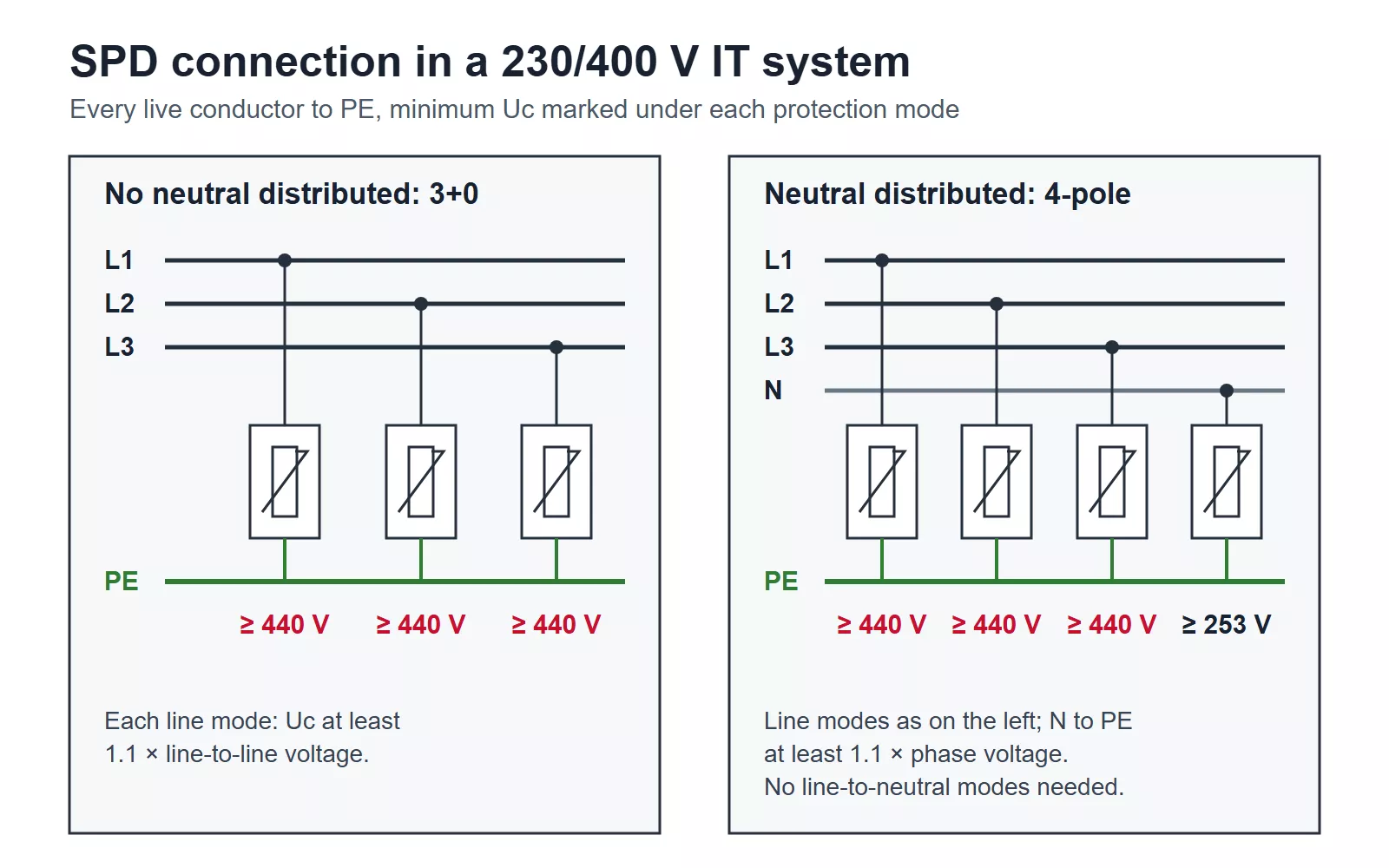
Figure 3 — SPD connection in an IT system: 3+0 without a distributed neutral and four-pole common-mode with one, with the minimum Uc marked on each branch.
The 3+1 assemblies used in TN-S and TT boards are built around line-to-neutral modes plus a single neutral-to-PE gap. In an IT system, differential-mode protection between line and neutral adds little, because lightning-induced surges arrive in common mode and, with no earthed neutral at the source, little of that surge is converted into a line-to-neutral voltage. What the IT system needs is every live conductor protected to PE at the right Uc, so a standard 3+1 module should not be dropped in as the IT answer even when a neutral is distributed.
Two more checks finish the selection. First, IEC 60364-4-44 Table 443.2 treats a 220–240 V IT system as a 230/400 V system when choosing the required impulse withstand voltage of equipment, again because of the voltage to earth during a fault, so the protection level Up is coordinated against that row. Second, the MOV energy rating (In, Imax) follows the same lightning exposure assessment as any other system; IT changes the voltage rating and the connection, not the surge current.
For a 230 V line-to-line IT supply, such as a single-phase medical isolating transformer output or the Norwegian public network, the line-to-PE minimum is 253 V and standard 275 V or 320 V devices meet it. Thor’s AC surge protection devices include the TRS2-C40 Type 2 SPD in 2P and 4P versions with Uc of 275 V or 320 V from each pole to PE. For a 230/400 V IT earthing system, specify line-to-PE modes at 440 V or above, and check the datasheet for the Uc of every protection mode, not only the headline value.
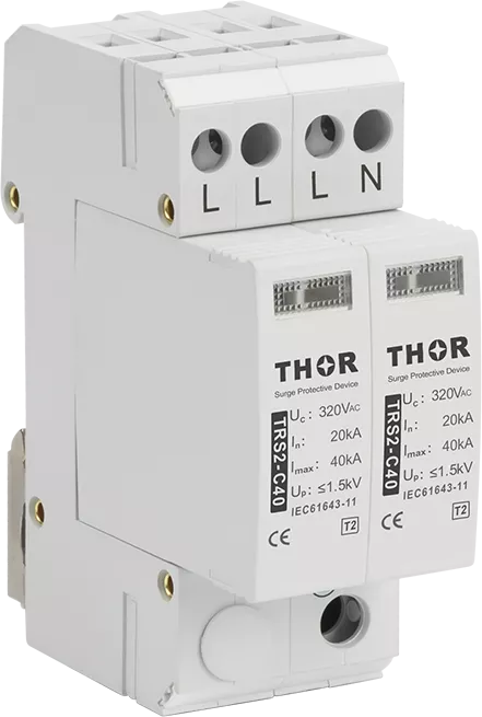
Figure 4 — Thor TRS2-C40 Type 2 SPD, 2P version rated Uc 320 V AC, suitable for a 230 V line-to-line IT circuit.
IT vs TN and TT earthing
The table puts IT beside the arrangements most installers work with every day.
| TN-S / TN-C-S | TT | IT | |
| Source star point | Solidly earthed | Solidly earthed | Isolated or high-impedance earthed |
| Where the installation’s PE comes from | Bonded to the earthed source, directly or through the supply network | Installation’s own electrode, independent of the source earth | Installation’s own electrode; the source itself is isolated or high-impedance earthed |
| First line-to-frame fault | Short circuit, disconnects | Limited by electrodes, disconnects by RCD | Small current; supply continues and the IMD or RCM alarms |
| SPD line-to-PE minimum Uc at 230/400 V | 253 V | 253 V | 440 V |
The separate guides to the TN-S earthing system and the types of earthing systems cover the other arrangements and their SPD connection in full.
FAQ
Is an IT earthing system used in UK homes?
No. UK public supplies are TN-C-S (PME), TN-S or TT. An IT earthing system appears in the UK inside specific installations, most often Group 2 medical locations fed from a medical isolating transformer, and in some industrial and marine supplies.
Can an IT system have a neutral?
Yes. An IT system can distribute a neutral, but the neutral is then insulated from earth like the line conductors and has to be monitored and protected in the same way. Second-fault calculations use the phase-to-neutral voltage, and the SPD needs a neutral-to-PE mode rated for at least 1.1 U/√3. Many designers leave the neutral undistributed to keep both simpler.
Does an IT earthing system still need an earth electrode?
Yes. The source is isolated, but every exposed-conductive-part is earthed through the installation electrode. The electrode resistance decides whether a first fault produces a safe touch voltage, so it has to be low enough that the resistance multiplied by the first-fault current stays at or below 50 V a.c.