
A TT earthing system (Terre-Terre) has the source neutral earthed at the transformer, while the consumer installs their own independent earth electrode on site. The fault loop impedance through that local electrode is too high for overcurrent protective devices to trip reliably — TT systems depend on RCDs for fault disconnection. Three-phase installations use four conductors from the supply, plus a local PE from the site electrode.
What Is a TT Earthing System?
The name TT comes from the French word Terre (earth) — the first T refers to the earthed source neutral at the transformer, the second T to the consumer’s own independent earth electrode. IEC 60364-1 defines five earthing system types: TN-C, TN-S, TN-C-S, TT, and IT. TT is the only one where the consumer’s protective earth has no metallic connection back to the source.
TT is common in areas served by overhead distribution lines, rural installations, and sites where the distributor does not offer a TN earthing facility. In these contexts, the IET guidance on TT earthing notes that the system is often the only practical option available.
TT Earthing System Wiring Diagram
A TT earthing system delivers three-phase power over four conductors: L1, L2, L3, and N. No PE comes from the distributor. At the installation, a local earth electrode — typically a copper-clad steel rod driven into the ground near the building entry point — connects to the main earthing terminal (MET), and the PE conductor runs from there to all equipment enclosures and exposed conductive parts. Figure 1 illustrates this arrangement.
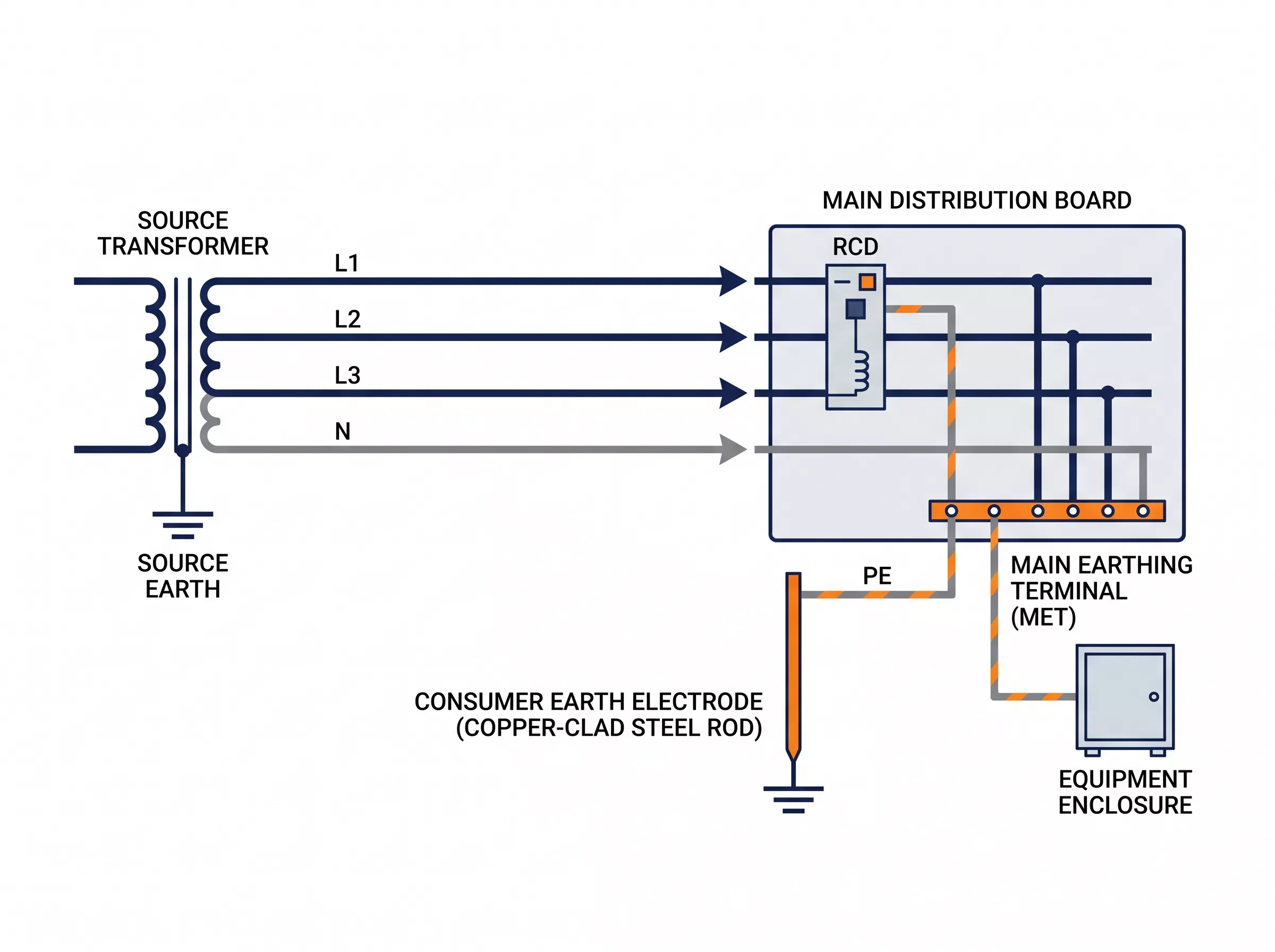
Figure 1 — TT earthing system wiring diagram: four-wire supply (L1, L2, L3, N) from transformer, consumer-side earth electrode connected to MET, PE running from MET to equipment enclosures
The separation between the source earth and the consumer earth is the defining feature of TT earthing system. Current flowing through a fault to PE returns to the source via the soil, not via a metallic conductor. The soil return path is inherently high-impedance and unpredictable — soil resistivity varies with moisture content, temperature, and depth, and a fixed Ze value cannot be assumed at design stage without on-site measurement.
Under IEC 60364-4-41 a TT earthing system protected by a 30 mA RCD must maintain Ze ≤ 1667 Ω. In practice, values below 200 Ω are recommended to account for seasonal soil resistivity variation and electrode aging. An earth rod in dry sandy soil can exceed 500 Ω without additional treatment — measure before commissioning, not after.
Advantages and Disadvantages of TT Earthing Systems
The TT earthing system is the default in many regions where the distributor does not offer a TN earthing facility. Its independence from the supply network is both its main strength and the source of its constraints.
The consumer earth electrode has no electrical connection to the source neutral. A fault on the supply side — including PEN conductor damage in a TN-C-S network nearby — cannot propagate dangerous voltages onto the local PE. For installations in areas where supply infrastructure is aging or unreliable, that isolation is a genuine safety advantage.
The mandatory RCD requirement cuts both ways. RCDs at 30 mA protect against earth faults and indirect contact at impedance levels that would never trip a fuse or circuit breaker. The tradeoff is nuisance tripping: equipment with high leakage currents — variable speed drives, long cable runs, IT equipment with EMC filters — can accumulate enough leakage to trip a 30 mA RCD under normal operation.
Selective RCD coordination reduces outage scope when a fault occurs. The standard arrangement pairs a Type S time-delayed RCD at the incomer (typically 100 mA, 300 ms delay) with Type AC instantaneous RCDs at outgoing circuits (30 mA) — the time delay prevents the upstream device from tripping on a downstream fault, isolating only the affected circuit.
In practice, total leakage current across all connected equipment should stay below 30% of the RCD trip threshold — for a 30 mA device, that means keeping system leakage below 10 mA. Variable speed drives alone can contribute 3–5 mA each; a distribution board feeding ten drives may already be close to the limit before any fault occurs.
| TT Earthing System | |
| Supply conductors (3-phase) | 4 (L1, L2, L3, N) |
| PE source | Local earth electrode |
| Fault loop impedance (Ze) | High and variable — soil-dependent |
| Fault disconnection | RCD required — OCPD alone insufficient |
| Supply-side fault isolation | Complete — no metallic path to source |
| Nuisance tripping risk | Higher than TN — leakage current accumulation |
| RCD selectivity | Required — upstream/downstream time coordination |
| Earth electrode maintenance | Periodic resistance measurement needed |
| Typical applications | Rural supplies, EV charging, overhead line areas, sites without TN facility |
TT vs TN-S vs TN-C-S: Key Differences
The three systems differ in one fundamental way: where the consumer’s protective earth comes from. In TN-S and TN-C-S, the distributor provides it — either as a dedicated PE conductor or split from a PEN at the building entry. In TT earthing system, the consumer is on their own. A single difference in earth source cascades into fault current levels, disconnection method, SPD connection mode, and installation cost.
The TN-C-S earthing system splits its PEN conductor at the building entry into separate N and PE, giving the internal installation a clean earth reference while keeping supply-side cabling to four conductors. The TN-S earthing system runs separate N and PE all the way from the transformer — the highest cost, the cleanest earth. TT runs four conductors from the supply and generates its own PE locally — Figure 2 illustrates the conductor arrangement and earth connection method for all three systems side by side.
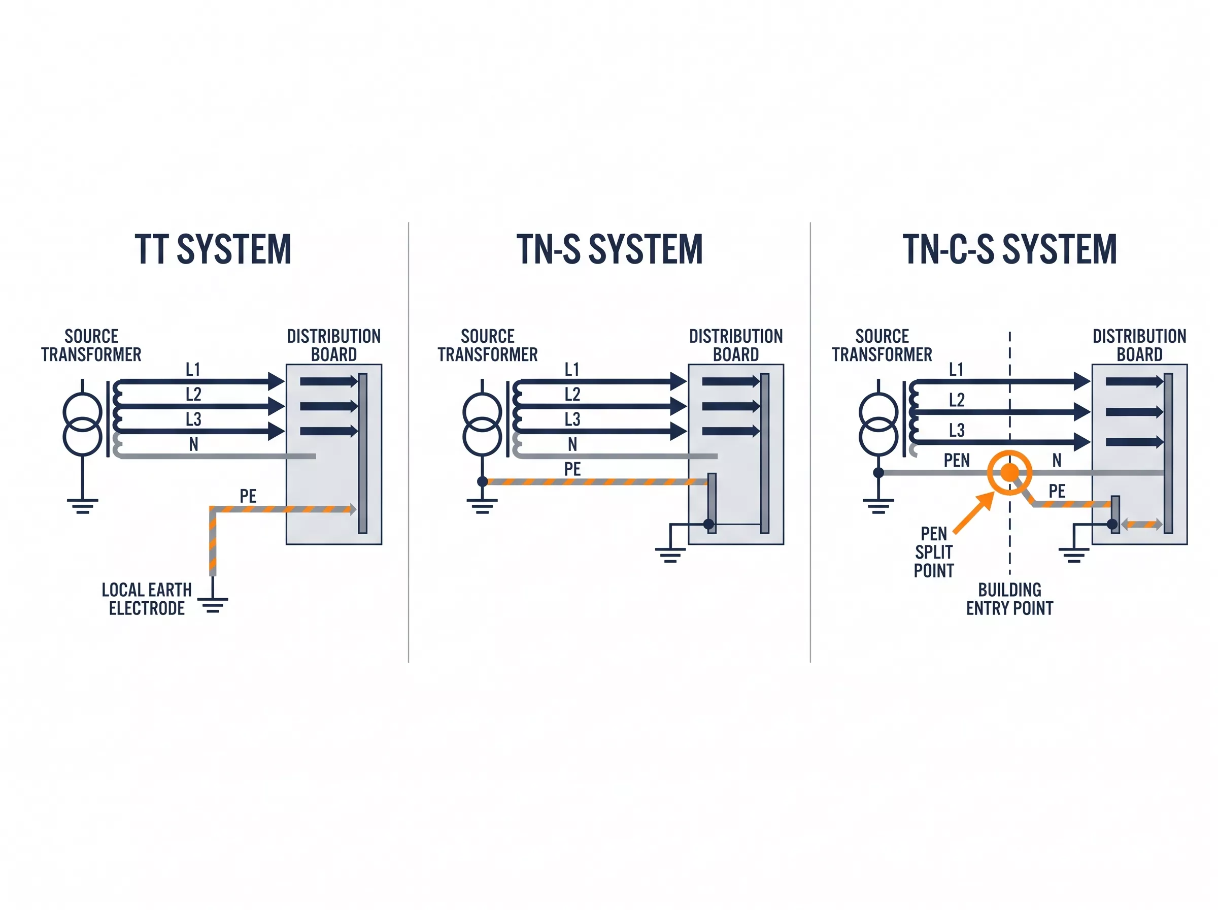
Figure 2 — TT, TN-S and TN-C-S earthing system comparison: conductor arrangement and earth connection method for each system
| TT | TN-S | TN-C-S | |
| Supply conductors (3-phase) | 4 (L1, L2, L3, N) | 5 (L1, L2, L3, N, PE) | 4 (L1, L2, L3, PEN) |
| PE source | Local earth electrode | Source transformer | Split at building entry |
| Fault loop impedance | High — soil dependent | Low — metallic path | Low — metallic path |
| Fault disconnection | RCD mandatory | OCPD sufficient | OCPD sufficient |
| PEN failure risk | Not applicable | Not applicable | Exists |
| N-PE noise isolation | Complete | Complete | Partial |
| SPD connection (3-phase) | 3+1 | 3+1 | 3+1 |
| Installation cost | Lower supply cost; local electrode needed | Highest | Mid |
| Typical use | Rural, overhead line areas | Industrial, sensitive loads | Commercial buildings |
SPD Configuration for TT Systems
TT earthing system installations use 3+1 connection mode for three-phase systems — L1, L2, and L3 each connect to PE through one MOV, and N connects to PE through a separate MOV. Single-phase TT uses 1+1: L to PE, and N to PE independently. For a full explanation of why 3+1 rather than 4+0, the 4+0 and 3+1 configuration article covers the wiring logic in detail.
Why not use a GDT-based SPD in TT systems? GDTs have lower insertion loss and carry higher impulse currents, but they introduce a follow current problem: once a GDT conducts, the power-frequency voltage can sustain the arc, creating a continuous short-circuit path to PE. In a TT earthing system where the PE path already has high impedance, that sustained arc may not generate enough fault current to trip the backup OCPD — making GDT-only SPDs unsuitable for TT installations. MOV-based SPDs self-recover when the surge passes, with no follow current risk.
One difference sets TT earthing system apart from TN systems. In a TT installation, the PE conductor runs through the local earth electrode before reaching the source — that path carries higher impedance than the metallic PE in a TN-S system. Under surge conditions, a higher PE impedance means more voltage appears across the protected equipment even after the SPD operates. Specifying an SPD with a lower Up rating gives more margin in TT installations than the same device would deliver in a TN system.
In a TT installation, the SPD installs on the supply side of the main RCD — upstream, not downstream. Placing a Type 2 SPD downstream of a 30 mA RCD risks nuisance tripping during surge events, as the surge current through the SPD’s earth path can exceed the RCD’s operating threshold. Where a time-delayed incomer RCD is used, the SPD may be placed downstream provided the manufacturer’s installation instructions permit it. Figure 3 shows the recommended arrangement.
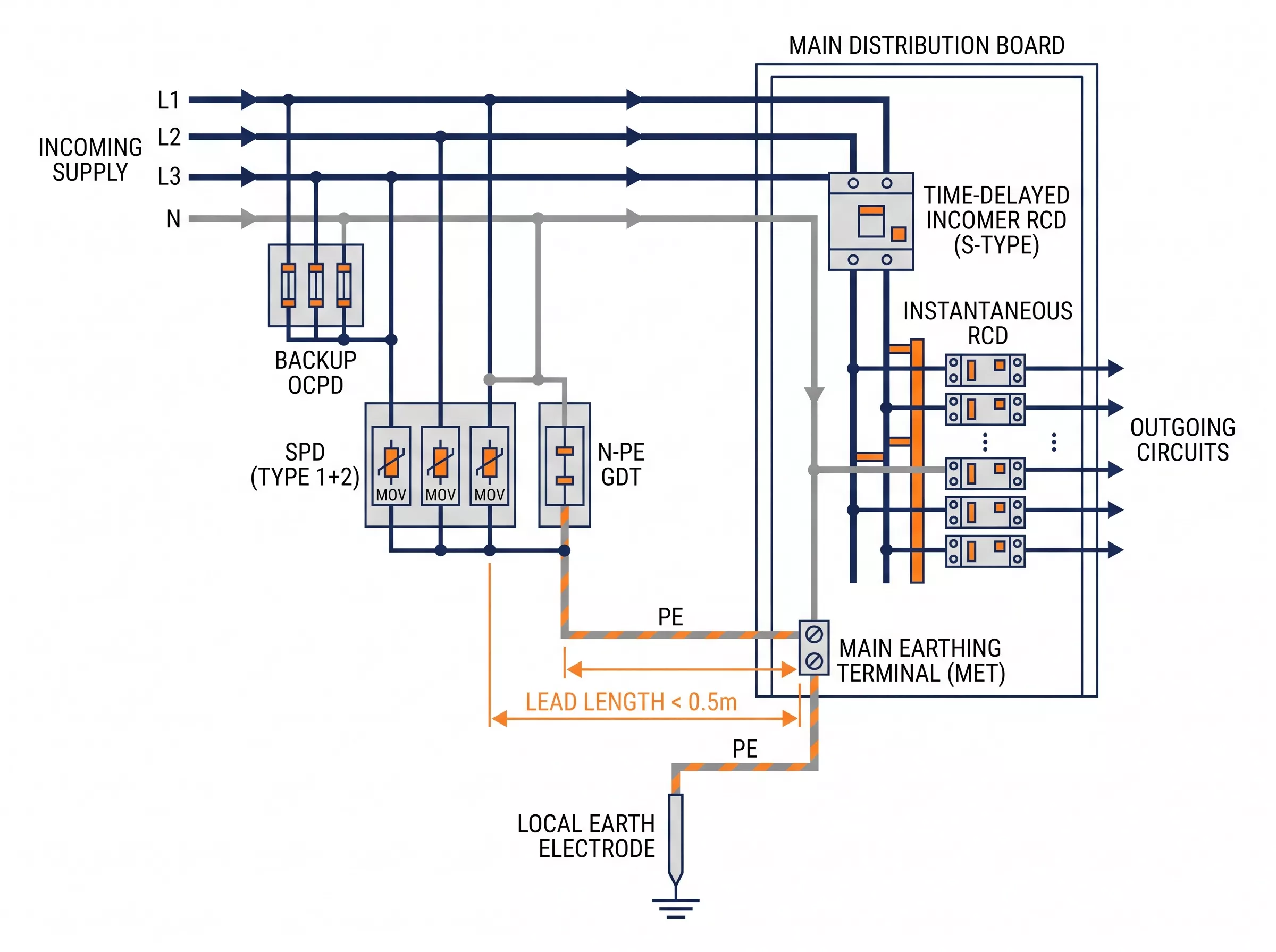
Figure 3 — TT system SPD and RCD installation arrangement: SPD on supply side (upstream) of main RCD, with backup OCPD in series with SPD
For most TT commercial and light industrial installations, Thor’s TRS4-C40 covers the standard requirement: In 20 kA, Imax 40 kA, Uc 275 V AC, Up ≤1.5 kV, certified to IEC 61643-11, in 3P+N configuration for direct 3+1 deployment. For installations in high keraunic zones or where an external lightning protection system is present, step up to the TRS5-B+C Type 1+2: Iimp 12.5 kA, In 20 kA, Imax 50 kA, Up ≤1.3 kV.
All Thor Electric SPDs are certified to IEC, TUV, CE, RoHS, CB and ISO standards.
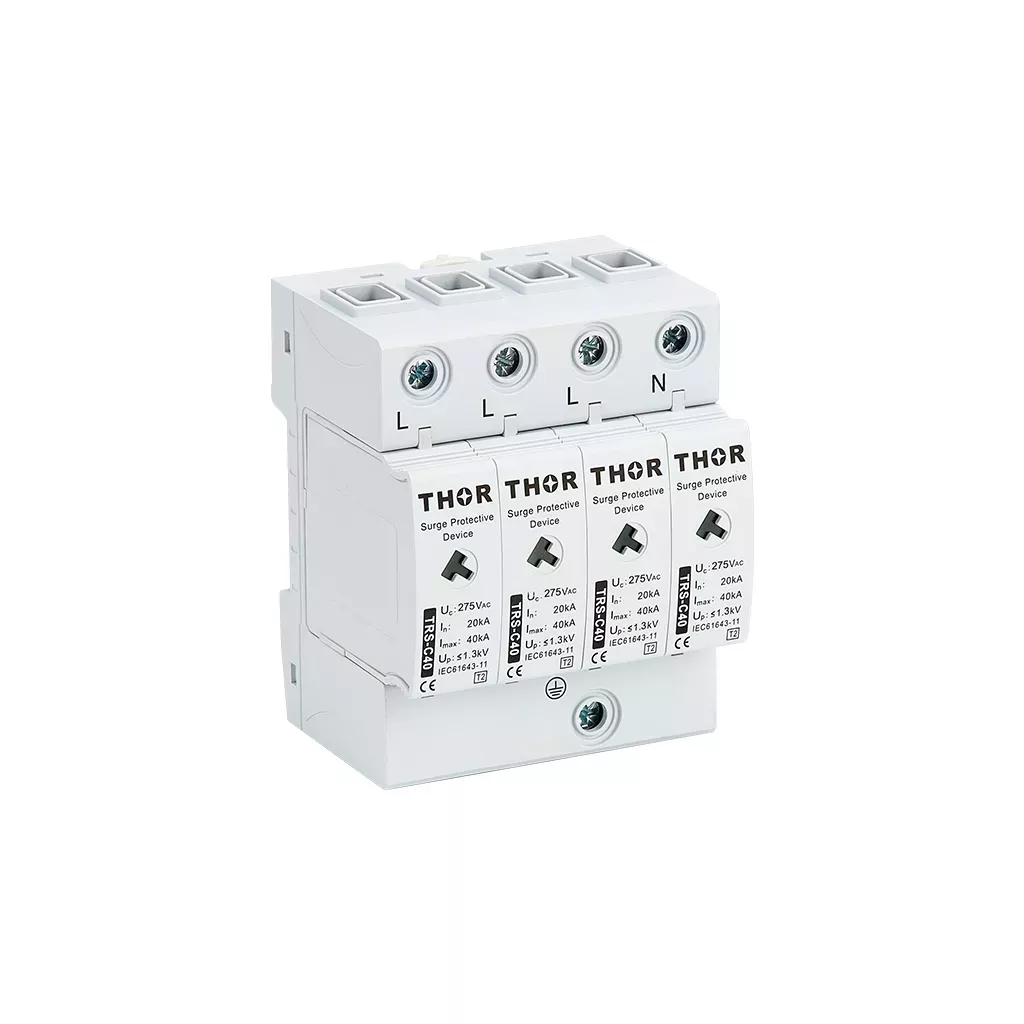
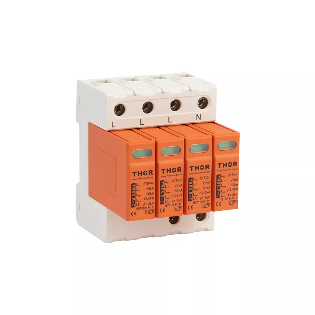
Figure 4 — Thor TRS4-C40 Type 2 AC SPD and TRS5-B+C Type 1+2 AC SPD, both in 3P+N configuration for TT three-phase installations
As shown in Figure 5, total lead length — line conductor plus PE conductor combined — must stay below 0.5 metres. Each additional metre adds roughly 1 μH of parasitic inductance, which at a surge rise rate of 10 kA/μs translates to 10 kV of additional voltage on top of the SPD’s rated Up.
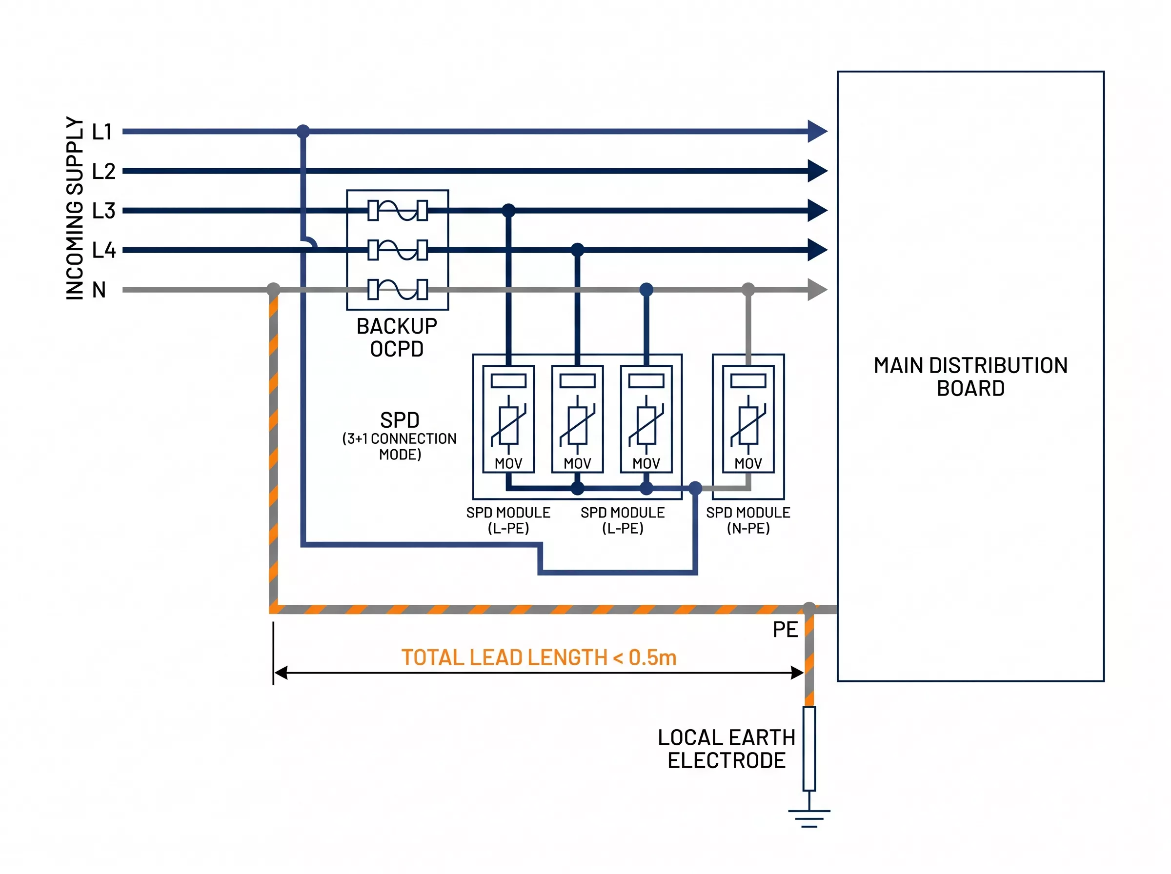
Figure 5 — SPD 3+1 connection diagram for TT three-phase system: L1, L2, L3 to PE through MOVs, N to PE through separate MOV, lead length ≤0.5 m
FAQ
What is a TT earthing system?
A TT earthing system is a grounding arrangement where the source neutral is earthed at the transformer and the consumer installs an independent local earth electrode on site — no PE conductor comes from the distributor. Three-phase TT supplies use four conductors: L1, L2, L3, and N. Because the fault current return path runs through soil rather than a metallic conductor, loop impedance is high and variable, making RCDs mandatory for reliable fault disconnection.
What is the difference between TT and TN earthing systems?
In a TN earthing system — whether TN-S or TN-C-S — the distributor provides a metallic PE or PEN conductor back to the source transformer, giving a low-impedance fault return path that trips overcurrent devices reliably. In a TT earthing system, the fault return path runs through soil to a local earth electrode, producing high loop impedance that standard fuses and circuit breakers cannot clear — which is why RCDs are mandatory. The TN-S earthing system and TN-C-S earthing system articles cover each in full.
Does a TT earthing system need an RCD?
Yes. A TT system relies on the local earth electrode for fault current return, and the loop impedance is almost always too high to trip a standard circuit breaker or fuse within the disconnection time required by IEC 60364-4-41. An RCD rated at 30 mA protects at impedance values up to 1667 Ω, which covers all practical TT installations. Without RCDs, a TT system has no reliable automatic disconnection on an earth fault.
What is the maximum earth fault loop impedance for a TT earthing system?
Under IEC 60364-4-41, a TT earthing system installation protected by a 30 mA RCD must maintain Ze ≤ 1667 Ω at the origin of the installation. In practice, values below 200 Ω are recommended — seasonal soil resistivity variation and electrode aging can push resistance upward over time, and the 200 Ω target preserves adequate margin. Earth electrode resistance should be measured at commissioning and checked periodically thereafter.
What SPD connection mode does a TT system require?
Three-phase TT installations use 3+1 connection mode: L1, L2, and L3 each connect to PE through a MOV, and N connects to PE through a separate MOV. Single-phase TT uses 1+1: L to PE and N to PE independently. Because the local earth electrode adds impedance to the PE path, specifying an SPD with a lower Up rating gives more effective protection in TT installations than the same device would deliver in a TN system.
Thor Electric AC Surge Protection Devices
Thor Electric manufactures Type 1, Type 2, and Type 1+2 AC SPDs certified to IEC 61643-11, covering single-phase and three-phase installations across TT, TN-S, and TN-C-S earthing systems. The TRS4 and TRS5 series are available in 3P+N configuration for direct 3+1 deployment in TT distribution boards, with samples and custom Uc variants available on request. For project-specific SPD specifications or bulk procurement inquiries, contact the Thor Electric team.