
Telecom surge protection on a modern cell site is mostly about the copper that still runs between the tower and the equipment. The radio data travels over fibre, but the remote radio units on the tower still need a DC power feeder, the site still takes an AC supply, and microwave links and older coaxial feeders still bring conductors down the mast. Those are the routes a lightning strike takes to the electronics.
The rectifier end of a DC feeder that powers radios on the tower is normally protected. Whether the tower end, a coax port or a shielded cable route also needs an SPD, and whether that SPD has to be a Type 1 device, depends on the site’s risk assessment, how the cable is screened and bonded, and what the equipment can withstand. ITU-T K.97 and K.56 set out that logic for telecom surge protection, and the sections below follow it one copper path at a time.
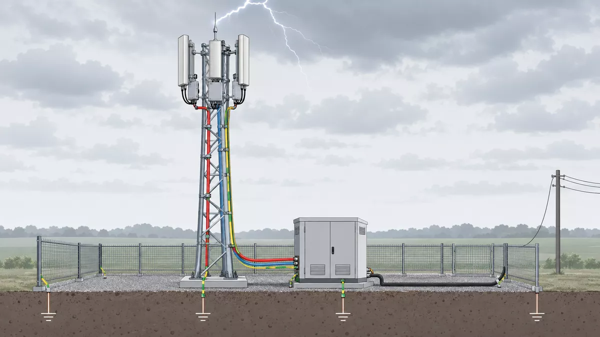
Figure 1 — Illustrative ground-mounted cell site: remote radio units on the tower, an equipment cabinet at the base and the cables that link them.
Where telecom surge protection goes on a cell site
Telecom surge protection on a cell site assesses every copper service that links the tower to the equipment: the DC feeder to the remote radio units, the AC mains supply, PoE radio links and any coaxial feeders. SPDs go where the risk and the current path call for them. The rectifier end of the DC feeder is normally protected; the tower end and shielded routes are checked against equipment withstand. Metal-free fibre needs no SPD.
Older sites ran every antenna back to the shelter on long coaxial feeders, with the radio electronics inside. On current sites the radio electronics move up the tower into remote radio units (RRUs) mounted beside the antennas. A fibre link connects each RRU to the baseband unit (BBU) in the shelter or cabinet, and a shielded multi-core copper cable, typically 6 to 16 mm², carries -48 V DC power up to them.
That change moved the lightning problem. The long coax runs that used to bring surge current into the shelter are mostly gone, and the DC feeder is now the conductor that runs the full height of the tower. The table sums up where telecom surge protection goes on each path; the numbers match Figure 2.
| No. | Copper path | Cable condition | Where protection normally goes | What decides it |
| 1 | DC feeder, rectifier end | Shielded or unshielded, RRUs on the tower | SPD downstream of the rectifier | Installed as the default; class from the site assessment |
| 2 | DC feeder, RRU end | Unshielded, no bonded metal duct | SPD before the RRU unless the RRU has equivalent protection built in | Required |
| 3 | DC feeder, RRU end | Shielded, or inside a continuous bonded metal duct | SPD only where the calculation calls for one | Expected common-mode voltage against RRU and cable withstand |
| 4 | AC mains | Incoming supply to the site board | First-stage SPD at the incoming point, second stage if needed | LPL, share of lightning current, earthing system, rectifier withstand |
| 5 | PoE radio link | Ethernet cable up the tower | SPD next to the radio unit on the tower and at the shelter entry beside the PoE injector or switch | Low protection level; must pass PoE power and data |
| 6 | Coaxial feeder | Legacy RF feeder or link cable | SPD where the expected voltage exceeds equipment withstand | Tower and cable shielding, cable length, port frequency |
| 7 | Fibre | Metal-free, or with a metallic strength member | No SPD for metal-free cable; bond any metal member at both ends | Cable construction |
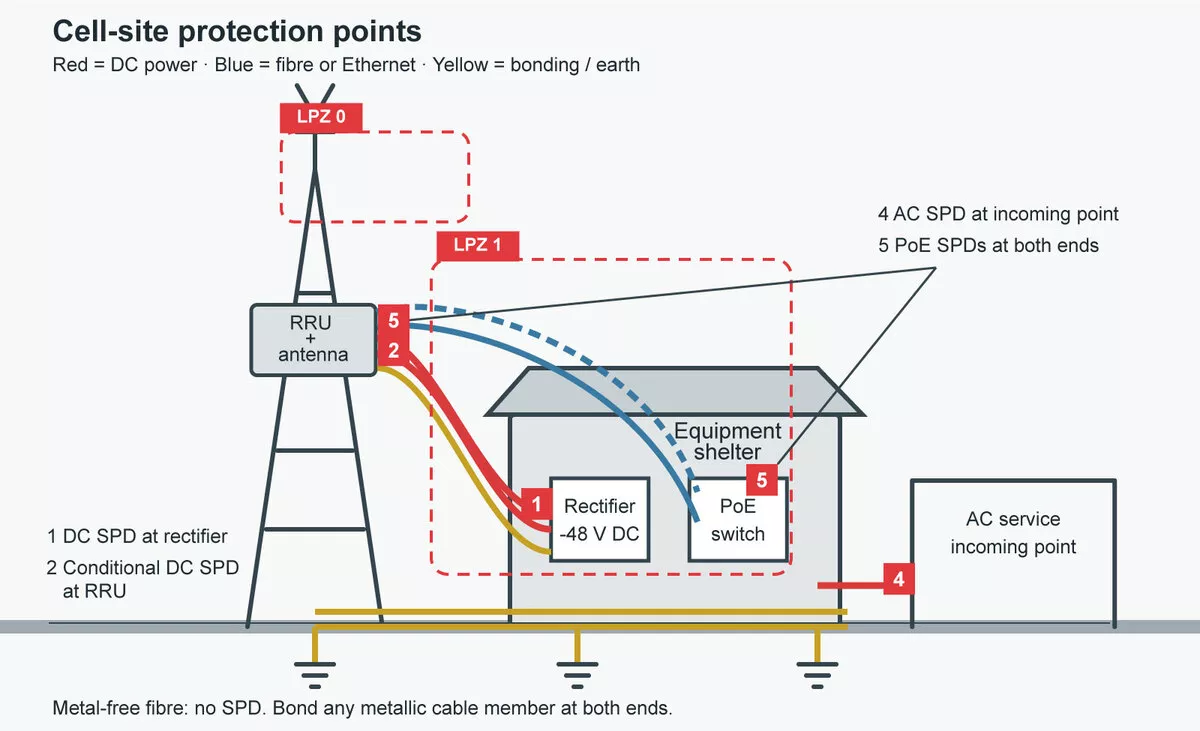
Figure 2 — Protection points on a ground-mounted cell site, numbered to match the table, with lightning protection zone boundaries around the tower and the equipment shelter.
What decides the protection: risk, cable and bonding
The same port can need a Type 1 SPD on one site and no SPD at all on the next. That is why telecom surge protection starts from the site. The two ITU-T recommendations written for base stations, K.56 for radio base stations with a shelter and tower and K.97 for distributed sites with RRUs, work towards the device in the same order:
- Risk assessment. Under IEC 62305-2, the operator’s tolerable risk of lost service sets the lightning protection level (LPL), and the LPL sets the lightning current the design has to carry. The risk assessment and LPL under IEC 62305 are covered step by step in a separate article.
- Current path. A strike to the tower divides between the tower structure, the earth-termination system and every conductive service that leaves the tower. The share each cable takes decides what its end protection has to carry.
- Cable construction and bonding. A continuous shield or metal duct, bonded at the tower and again at the shelter entry, carries most of that current on its outer surface and leaves a much smaller voltage between the inner conductors and the shield.
- Voltage at the port. From the current, the cable’s transfer impedance and its length, K.97 calculates the common-mode voltage expected at the equipment.
- Equipment withstand. If the equipment input and the cable insulation withstand that voltage, no separate module is needed. If they do not, an SPD goes in, and its class follows from the current it will see.
- Operator or radio-vendor specification. Many operators have their own protection rules, and those take precedence on their sites.
Air-termination and separation distance feed into steps 2 and 3. They weigh heavily in telecom surge protection, but they are inputs to the decision and cannot settle it alone.
Rooftop sites
On a rooftop site the antennas sit on a building that belongs to someone else, and the owner normally expects the installation to add no risk to it. The usual answer is an isolated air-termination: a rod on a non-conductive supporting tube, tall enough to hold the antennas, RRUs and cables inside its protected volume, with its down conductor kept at the separation distance from the antenna installation. Direct and partial lightning current then reaches earth through the building’s lightning protection system without using the antenna mounting, the DC feeder or the building’s internal services as a path. Induced surges on those cables remain, so the port assessment still applies.
Where the separation distance cannot be held, the antenna structure is bonded to the lightning protection system instead. The feeder then has to be treated as a path for partial lightning current, and the protection at both of its ends is sized accordingly.
Ground-mounted sites
A ground-mounted tower is the strike point. K.56 builds the earthing around ring electrodes at the tower, the shelter and the fence, joined by several interconnections, so the lightning current has a controlled path into the ground and the voltage gradient across the site surface stays low. Generators, PV racks and outdoor cabinets join the same bonded system.
Two points in K.56 are easy to miss when planning telecom surge protection on a tower site. Earth resistance is not the prime protection parameter: a low reading helps limit surges passed into connected services, but the bonding layout matters more. And bonding controls the potential difference between structures; it does not prove that the DC conductors running down the tower carry no partial lightning current. All services should enter the shelter at one point, with every shield bonded to the entry earthing bar.
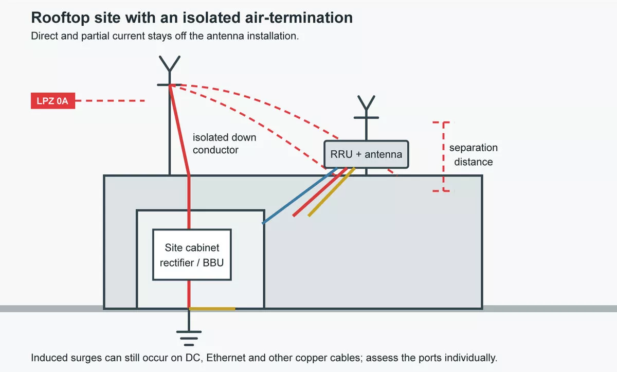
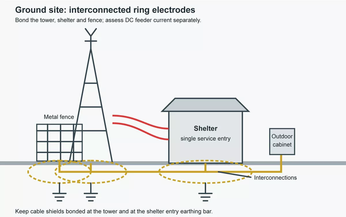
Figure 3 — Left: rooftop site with an isolated air-termination kept at the separation distance from the antenna installation. Right: ground-mounted site with ring electrodes at the tower, shelter and fence, joined by several interconnections.
Protecting the DC feeder to the remote radio units
The DC feeder is where most of the design effort in telecom surge protection now goes. It runs the full height of the tower, it connects the most exposed equipment on the site to the rectifiers and batteries, and its two ends follow different rules.
The rectifier end
ITU-T K.97 recommends a protection module downstream of the rectifier whenever the rectifier supplies RRUs installed on the tower, and it makes that recommendation for shielded and unshielded cable alike. Whatever the feeder picks up on the tower arrives at the rectifier, which serves every radio on the site. When the RRU sits inside the shelter, the feeder never leaves the building and the conventional K.56 approach applies instead.
The RRU end
At the top of the tower, the answer depends on the cable. An unshielded feeder without a continuous bonded metal duct needs a protection module before the RRU, unless the RRU already has equivalent protection built in.
A shielded feeder, or an unshielded one inside a bonded duct, is assessed. K.97 works out the common-mode voltage expected between the conductors and the shield from four inputs: the LPL current, how that current divides between the tower and the cable, the cable’s transfer impedance and its length. If the result stays below both the RRU’s DC input withstand and the cable’s conductor-to-screen withstand, the module at the RRU can be left out. K.97’s informative example of an isolated layout goes one step further and shows a bonding arrangement where the rectifier-side module can also be optional.
The calculation cuts both ways. It can take a module off a well-shielded route, and it can show that a route assumed to be safe needs one. Skipping it is how telecom surge protection ends up either overbuilt or missing at the top of the tower.
Either way, the shield only does its job if it is continuous and bonded at the tower end and again near the shelter feed-through or through the protection module. The RRU and its protection module are bonded to the tower structure, or to a bonding bar next to it, with a short conductor.
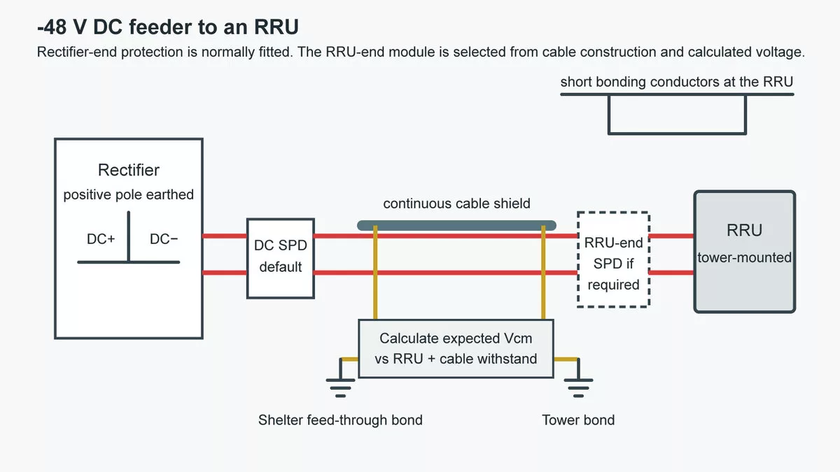
Figure 4 — A -48 V DC feeder from a rectifier with its positive pole earthed to an RRU on the tower: protection downstream of the rectifier, conditional protection at the RRU, and shield bonding at the tower and at the shelter feed-through.
Type 1 or Type 2 at each end
Once the analysis says a module is needed, its class follows from what the port will see. Where the feeder can carry partial lightning current, typically an unshielded route on a tower that is itself the strike point, the SPD needs a Type 1 rating tested with the 10/350 µs lightning impulse current. Where the shield, the duct and the bonding keep the duty down to induced surges, a Type 2 SPD tested with 8/20 µs impulses and a low voltage protection level is the usual choice, and some operators specify their RRU feeders that way.
In telecom surge protection the order matters: settle the site analysis and the operator’s specification first, then pick the class. A Type 2 device on a port the analysis shows carrying lightning current is the mistake to avoid.
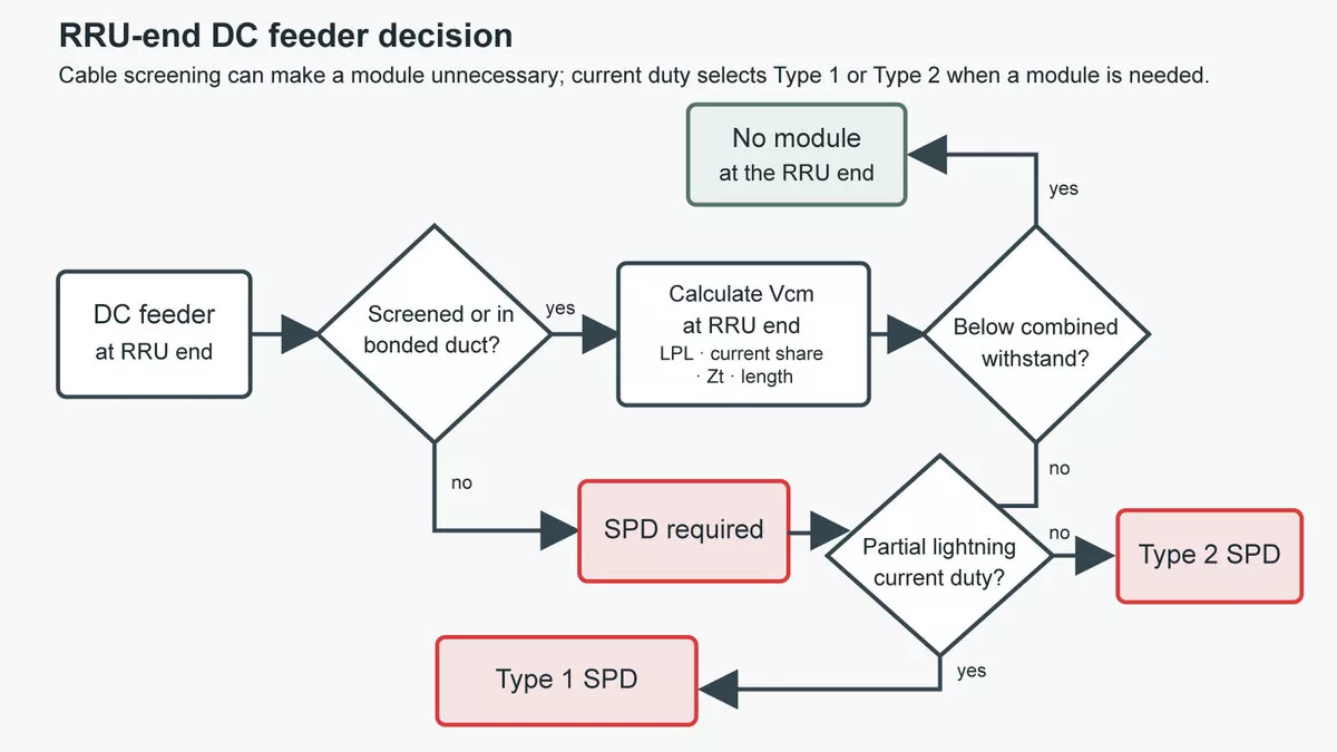
Figure 5 — Deciding the protection at the RRU end of the DC feeder: cable construction, calculated common-mode voltage against withstand, then no module, a Type 2 SPD or a Type 1 SPD.
Choosing Uc and Up on a -48 V system
Telecom DC plants usually run at -48 V with the positive pole earthed at the power supply. The live negative conductor is protected against earth, and at the tower end a common arrangement links the positive conductor to the cable shield through a spark gap instead of a solid bond, which avoids corrosion and stray currents. Two ratings then do most of the work:
- Maximum continuous operating voltage (Uc). It must sit above the highest voltage the system reaches in service, including battery float and equalise charging, so the SPD never conducts in normal operation. Check it against the highest setting the rectifier allows, not the 48 V nominal figure.
- Voltage protection level (Up). Up plus the voltage across the connecting leads has to stay below the input withstand of the RRU or rectifier. At surge currents the leads add a substantial voltage of their own, so keep them short.
Where the analysis lands on Type 2, the Thor TRS3-C40 DC is built for this voltage class. Its 48 V version is rated as follows:
| Parameter | TRS3-C40 DC, 48 V version |
| Nominal voltage Un | 48 V DC |
| Maximum continuous operating voltage Uc | 65 V DC |
| Nominal discharge current In (8/20 µs) | 20 kA |
| Maximum discharge current Imax (8/20 µs) | 40 kA |
| Voltage protection level Up | ≤0.7 kV |
| Response time | <25 ns |
| Remote signalling | Optional |
The same low-voltage TRS3-C40 range covers 24, 75 and 110 V DC systems. The formats are listed under DC surge protection devices, and the wider DC SPD selection guide covers DC applications outside telecom.
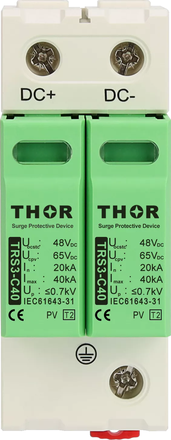
Figure 6 — Thor TRS3-C40 DC Type 2 surge protective device for 48 V DC systems.
AC mains at the site distribution board
The AC side is the most familiar part of telecom surge protection, but a cell site adds two conditions. The rectifiers behind the board are the load that matters most, and an SPD operation that trips the incoming protection takes every radio off air.
Where the building or plot allows, the site gets its own feeder and sub-distribution board, separate from the host building’s supply. The first-stage SPD goes at the incoming point. Its current rating comes from the LPL and the share of lightning current expected on the power service. A tower site has few conductive services leaving it, so each one, the power service included, takes a larger share of the current that does not go straight into the ground. That share can be high enough to call for a Type 1 or combined Type 1+2 device. Uc is checked under normal and fault conditions, since a neutral fault or earth fault raises the voltage the SPD sees.
The connection type follows the supply system and the local installation rules:
| Supply system | Typical connection | What to confirm |
| TN-S or TN-C-S | CT1 (4+0) or CT2 (3+1) | Where the PEN conductor is split, the installation point and local rules |
| TT | CT2 (3+1), spark gap between N and PE | The neutral-to-earth path under fault conditions |
| IT | Line-to-PE modes, Uc rated for line-to-line voltage | Voltage on healthy lines during a first earth fault |
Whether a second stage is needed depends on the voltage that actually reaches the rectifier input. K.56 counts three parts: the SPD’s residual voltage, the inductive voltage across its connecting leads, and the voltage induced into the wiring between the SPD and the equipment. If the sum exceeds the rectifier’s withstand, a Type 2 stage goes in close to the rectifier, and the two stages have to be coordinated by test or by the manufacturer’s declaration.
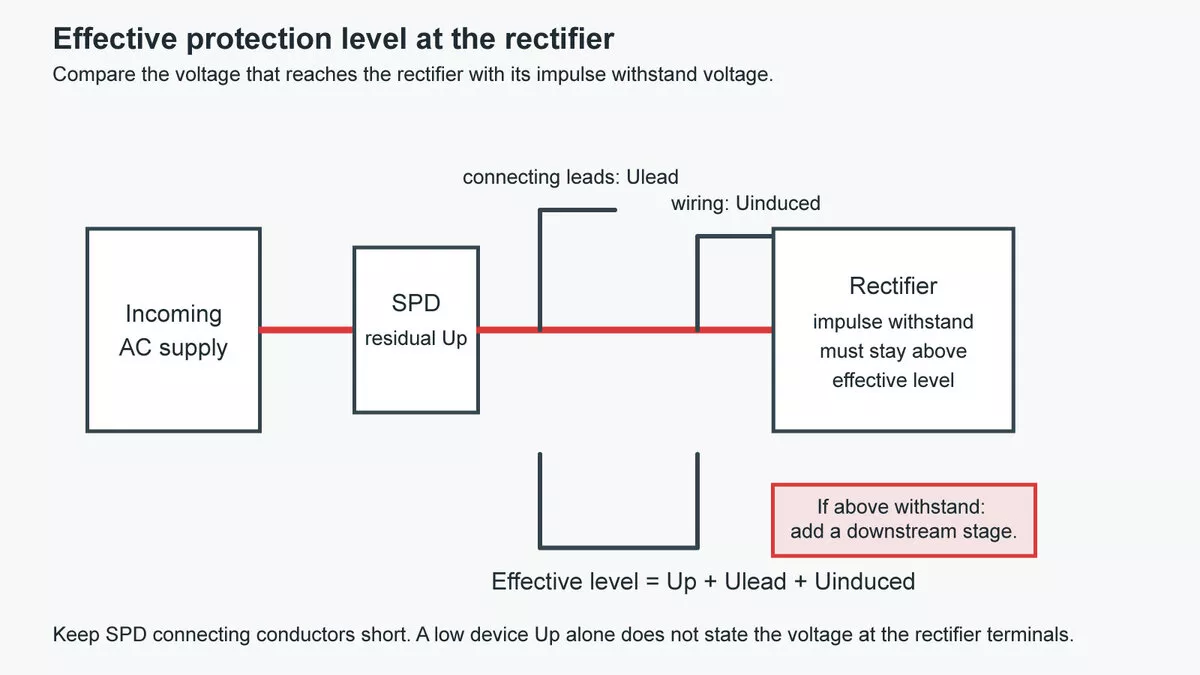
Figure 7 — The effective protection level at the rectifier: SPD residual voltage, connecting-lead voltage and induced wiring voltage added together and compared with the rectifier’s withstand.
Backup protection is a separate check. The fuse or breaker ahead of each SPD has to protect it without tripping on the surge current itself, and the incoming protection has to stay closed while the SPD operates.
Thor’s AC surge protection devices include the TRS-A graphite-gap Type 1 range (15, 25 and 50 kA Iimp), TRS8 Type 1+2 devices that combine MOV and GDT, and TRS-C40 Type 2 devices (In 20 kA, Imax 40 kA, Up ≤1.5 kV) for the stage near the rectifier. Pairing them into a coordinated set still goes through the coordination check above.
Other copper paths: radio links, coax, fixed lines and backup power
The remaining copper paths are shorter, and telecom surge protection on them follows the same site logic. Microwave links that carry the site’s backhaul are often powered over Ethernet. The conductors in an Ethernet cable are small, so the first job belongs to the external lightning protection: keep direct lightning current off the cable with the air-termination and by routing it inside the protected volume. Protection then goes at each end where the cable leaves protected space: next to the radio unit on the tower, and where the cable enters the shelter or cabinet, beside the PoE injector or switch. The SPD needs a low protection level and has to pass the PoE supply and the data without interruption. Thor’s TRSS-RJ45 range is rated Uc 57 V for PoE with a 250 MHz cut-off frequency, and its IP68 version mounts outdoors at the tower end. The reasons sealing matters there are covered in outdoor RJ45 surge protection, and the formats are listed under PoE surge protectors.
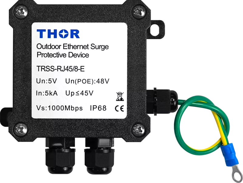
Figure 8 — Thor TRSS-RJ45 IP68 surge protector for outdoor Ethernet and PoE links.
Where coaxial feeders remain, K.56 applies the same logic as for the DC feeder. The voltage expected at the equipment follows from the LPL current, the shielding of the tower and the cable tray, and the cable’s transfer impedance and length; an SPD goes in where that voltage exceeds what the equipment withstands. A coax protector must also be rated for the highest frequency used on that port. Thor’s TRSW coaxial range (N, TNC, SMA and BNC connectors, 50 Ω, 10 kA) covers up to 2.5 GHz in its N, TNC and SMA versions.
A copper telephone or DSL line entering the site needs a telecom-line protector at the entry point, bonded to the same earthing bar as the other services.
Off-grid and hybrid sites often add a generator or a PV array with batteries. The generator frame and PV racks join the site earthing, and a PV SPD rated for the string voltage goes at the charge controller, since the large module area picks up induced surges from nearby strikes.
Keeping telecom surge protection working on unmanned sites
Most cell sites have nobody on them, which changes how telecom surge protection is maintained. An SPD that has reached end of life and disconnected itself stops protecting without any visible effect on service, and on a remote site it can stay that way until the next lightning fault brings a technician out. Three habits shorten that window:
- Wire remote signalling contacts into the site alarm system, so a disconnected SPD raises an alarm at the network operations centre. Thor’s TRS3-C40 DC and TRS8 devices carry remote signalling as an option.
- Choose pluggable modules where the series has them, so a technician replaces the module without rewiring the base.
- Check the indicator windows after each storm season and after any lightning-related fault.
FAQ
What is a telecom surge protector?
A telecom surge protector is an SPD installed on a telecommunications site or line. Telecom surge protection on a cell site uses three kinds of device: AC power SPDs on the mains supply, DC SPDs on the -48 V feeders to the radios, and signal-line SPDs on Ethernet, telephone and coaxial ports. The term is often used for the signal-line type alone, which is tested to IEC 61643-21.
Does a cell tower with a lightning rod still need surge protection?
Yes. The air-termination on the tower intercepts the strike and carries the current to earth, but part of that current and the voltages induced along the tower still reach the DC feeder, the AC supply and the data cables. SPDs limit what reaches the equipment at the ports where the site assessment shows a risk. The air-termination and telecom surge protection cover different risks: a tower site needs the lightning protection system plus SPDs at the ports the assessment identifies.
Which standards cover telecom surge protection at cell sites?
The IEC 62305 series covers lightning protection and the risk assessment that sets the LPL. SPDs are tested to the IEC 61643 part that matches the port: 61643-11 for AC power, 61643-21 for telecommunication and signalling lines, 61643-41 (first published in 2025) for general low-voltage DC power systems, and 61643-31 for the DC side of PV installations. For base stations, ITU-T K.56 covers radio base stations with a shelter and tower, and ITU-T K.97 covers distributed sites with remote radio units.
Specifying protection for a cell-site project
If you are specifying telecom surge protection for a site build or a rollout, send us the site type (rooftop or ground-mounted), the LPL from the risk assessment if one exists, the earthing system and AC supply arrangement, the DC nominal voltage and whether the RRU feeders are shielded, unshielded or ducted, and the data and RF interfaces with their connector types and highest frequency. We will review the site port by port and propose a protection schedule. Contact our engineering team.