
Install a Type 1 SPD at the service entrance and a Type 2 SPD in the distribution board, and you would expect them to share the surge in that order. In practice, the Type 2 often conducts first, absorbs energy it was never rated for, and fails early. SPD coordination is the design work that prevents this: matching device characteristics, separation distance, and protection levels so each stage takes the load it was built to take. We cover the SPD coordination method from IEC 61643-12, including what the well-known “10-meter rule” actually requires.
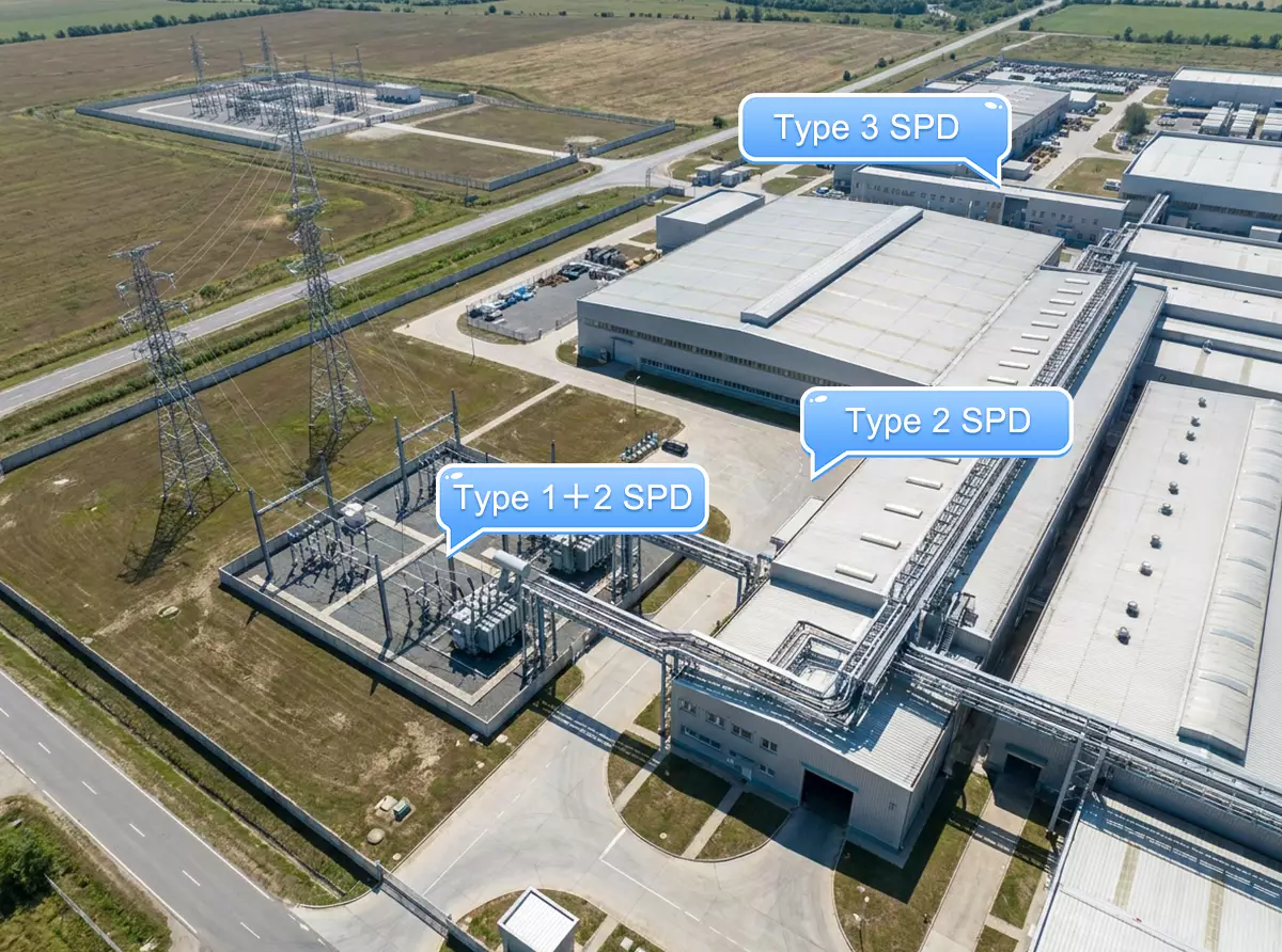
Figure 1 — A coordinated three-stage installation: Type 1 SPD at the main incoming panel, Type 2 in the downstream distribution board, Type 3 at the machine control cabinet.
FOREGROUND (site entrance, outdoor): an outdoor utility service point with an incoming power line from a distant pole, a compact outdoor switchgear cabinet at the plant’s electrical intake. Empty clean rectangular callout label box reading “Type 1 SPD – service entrance” pointing to this outdoor intake cabinet.
MID-GROUND (between intake and building): an outdoor transformer / distribution substation enclosure sitting in its own fenced yard several tens of meters from the main factory building, connected to the foreground intake by a visible cable trench or overhead line run. Empty callout label box reading “Type 2 SPD – distribution board” pointing to this substation.
BACKGROUND: a large complete factory building (full exterior of the industrial hall with walls and roof visible), with a cable route entering the building. Through an open roll-up door or as an inset, a terminal control cabinet inside near production machinery. Empty callout label box reading “Type 3 SPD – equipment” pointing to the in-building control cabinet.
The three zones are clearly separated by real distance and connected by visible power routing to show the electrical path from grid intake to end equipment. No visible SPD devices — leave marked locations clear. No brand logos. English labels only, sentence case.
What is SPD coordination?
SPD coordination is the deliberate matching of cascaded surge protective devices so that the upstream SPD (Type 1) absorbs the main surge energy before the downstream SPD (Type 2 or Type 3) conducts. Per IEC 61643-12, coordination is verified through energy criteria: the energy passed to each downstream stage must stay below that device’s maximum energy withstand.
Why a single SPD can’t do the job
A direct or nearby lightning strike injects a 10/350µs impulse carrying far more energy than any panel-mounted MOV device can survive. A Type 1 SPD at the service entrance is built for exactly this waveform. But its job is energy diversion, not fine protection. A Type 1 device like the Thor TRS-A25 clamps at Up ≤2.2kV, which is low enough to protect the installation wiring but too high for a PLC rated to withstand 1.5kV.
The reverse is also true. A Type 2 SPD clamps low enough for equipment (Up ≤1.5kV on the TRS-C40) but is tested only with the 8/20µs waveform. Feed it partial lightning current and it absorbs 10–20 times its rated energy. The failure is not gradual.
Each stage covers what the other cannot. The cascade follows the lightning protection zone concept: the Type 1 SPD at the LPZ 0→1 boundary takes the impulse current, the Type 2 SPD at the next distribution level cuts the residual to equipment-safe levels, and a Type 3 SPD covers the last meters where needed.
As shown in Figure 2, each boundary crossing steps the surge environment down to a level the next stage can manage.
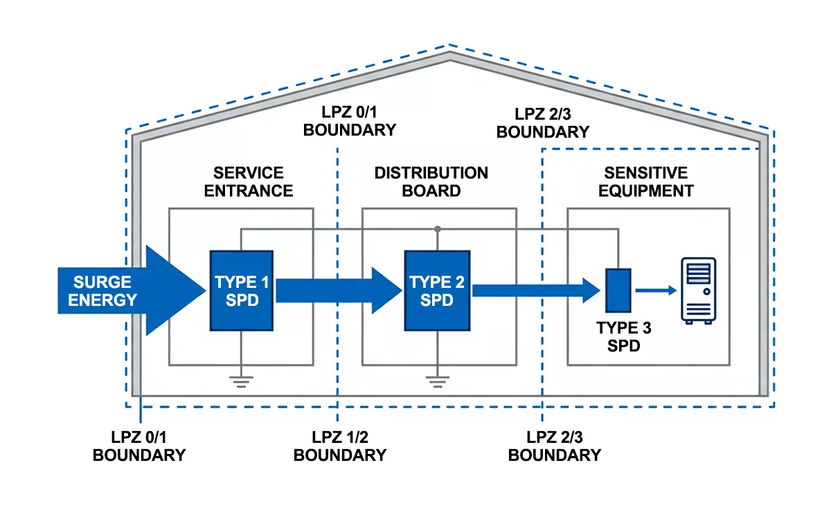
Figure 2 — Three-stage SPD coordination across LPZ boundaries — each stage reduces surge energy to a level the next device can withstand.
The 10-meter rule: what IEC 61643-12 actually says
Ask most installers about SPD coordination and you get one answer: keep 10 meters of cable between the Type 1 and Type 2 device. The number is real, but its status is widely misunderstood.
IEC 61643-12 does not mandate a 10-meter separation anywhere in its normative text. The requirement in clause 7.2.7 is energy coordination: for every surge current up to the upstream SPD’s rating, the energy passed through to the downstream SPD must stay below that device’s maximum energy withstand. Distance is one way to get there, not the rule itself.
The 10-meter figure comes from the standard’s informative Annex F. Installation cable carries roughly 1µH of inductance per meter, so 10m of cable adds about 10µH between the two stages. During a fast-rising surge, that inductance produces a voltage drop (L·di/dt) that pushes the upstream device into conduction before the downstream one. Manufacturer application guides turned this worked example into the “10m rule.”
Two practical consequences follow:
- Less than 10 meters is not automatically a violation. A decoupling inductor of around 10–20µH in the line achieves the same effect where panel layout makes the distance impossible. Annex F.3.2 of the standard shows the calculation method.
- More than 10 meters is not automatic compliance. If the downstream MOV’s V-I curve crosses the upstream device’s curve at low currents, the Type 2 still conducts first regardless of cable length. SPD coordination lives in the device characteristics, not the tape measure.
Figure 3 shows both arrangements side by side.
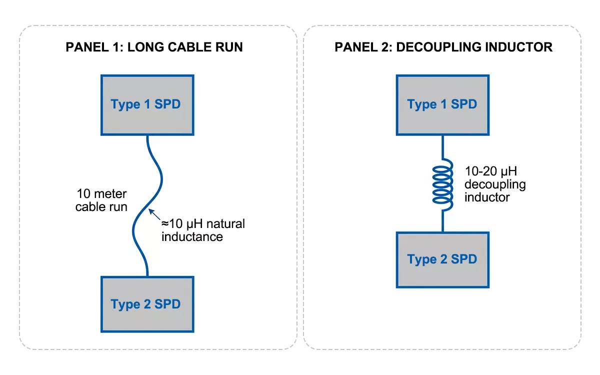
Figure 3 — Two ways to decouple cascaded SPDs — 10m of installation cable, or a decoupling inductor where the distance is not available.
Up gradient: matching protection levels across stages
Energy criteria decide whether an SPD coordination scheme survives. The voltage protection level (Up) gradient decides whether it fires in the right order.
The working rule: each downstream stage should clamp at a lower Up than the stage above it, with enough margin that normal tolerance spread doesn’t flip the sequence. IEC 61643-12 covers Up selection in clause 7.2.6, and a margin of around 20% between stages is the common design target.
Map that onto a real cascade. A Thor TRS-A25 Type 2 SPD at the entrance clamps at Up ≤2.2kV. A TRS-C40 in the distribution board clamps at Up ≤1.5kV, a 32% step down. A TRS-D20 in a sub-panel takes the final stage to ≤1.0kV. Each device protects the zone behind it at a level the previous stage could not reach, and the gradient descends cleanly.
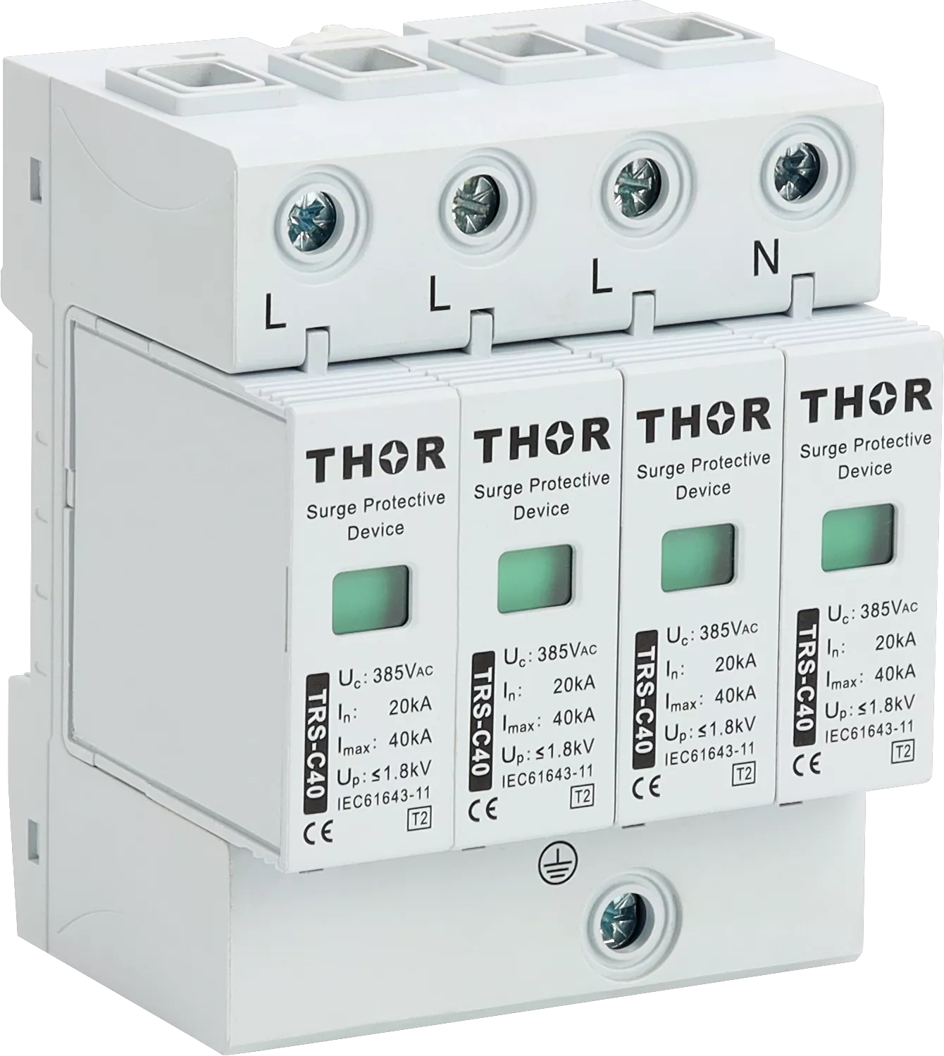
Figure 4 — Thor TRS-C40 Type 2 SPD — 40kA Imax (8/20µs), Up ≤1.5kV, visual fault indicator and optional remote signaling.
For two MOV-based devices, the check goes deeper than the two datasheet numbers. Up is a single point on each device’s V-I curve, measured at nominal discharge current. Coordination holds only if the curves stay apart across the whole current range. When an upstream MOV with a higher discharge rating and a downstream MOV with a lower one have curves that cross at low currents, the downstream device conducts first in exactly the region where most surges occur: small, frequent switching transients. The downstream MOV then ages fast while the upstream device sits idle. We see the result in the field as a Type 2 with a red fault indicator eighteen months after commissioning, next to a Type 1 that has never operated.
Figure 5 shows the two cases.
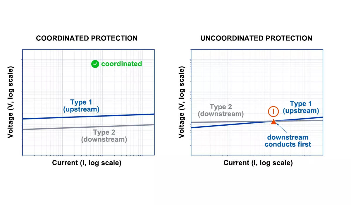
Figure 5 — V-I curves of cascaded MOV devices — coordination holds when curves stay separated (left); a low-current crossover puts the surge load on the downstream device (right).
LEFT graph titled “COORDINATED PROTECTION”: the blue Type 1 curve stays ABOVE the gray Type 2 curve across the ENTIRE current range — the two curves never touch or cross at any point, blue consistently higher than gray from low to high current. Green checkmark icon with label “coordinated”. Label the blue curve “Type 1 (upstream)” and gray curve “Type 2 (downstream)”.
RIGHT graph titled “UNCOORDINATED PROTECTION”: the two curves CROSS in the LOW-CURRENT region on the left side of the graph — at low current the gray Type 2 curve sits ABOVE the blue Type 1 curve, they intersect, then blue rises above gray at higher current. Red warning triangle at the crossover point with a callout arrow labeled “downstream conducts first”. Same curve labels.
Sans-serif labels in English, sentence-case, no duplication.
One caveat closes this section: the Up gradient method assumes both devices are voltage-limiting. Put a voltage-switching device upstream, such as a spark gap or graphite gap Type 1, and the gradient check alone is no longer sufficient. That combination needs its own analysis.
Gap-to-MOV coordination: when the gradient rule breaks down
A graphite gap Type 1 SPD and an MOV Type 2 SPD behave nothing alike before a surge arrives, and that difference is where most SPD coordination failures start.
An MOV conducts progressively. Its V-I curve is continuous: as voltage rises, current through the varistor rises with it, well before the nominal clamping point. A gap device does the opposite: near-infinite impedance until the ignition voltage is reached, then an abrupt switch to a low-impedance arc. Between those two behaviors sits a dangerous window. The surge voltage climbs, the downstream MOV is already conducting, and the upstream gap has not yet fired. Every ampere in that window flows through the device with the smaller energy rating.
IEC 61643-12 treats this combination separately in Annex F.3, and states plainly that a Up comparison is not enough for gap-to-MOV cascades. The decoupling impedance between the stages has to generate enough voltage drop, fast enough, to push the gap past ignition before the MOV takes significant energy. The calculation in Annex F.3.2 works from three inputs: the gap’s ignition voltage tolerance, the MOV’s residual voltage at the expected current, and the surge’s rate of rise.
We build one configuration more than any other: a TRS-A series graphite gap device at the entrance, TRS-B or TRS-C MOV devices downstream. The TRS-A fires in under 100ns once ignition voltage is reached, and the arc then diverts the 10/350µs impulse at up to 50kA Iimp on the TRS-A50. But that ignition threshold is exactly why the decoupling stage matters more here than in an MOV-to-MOV cascade. Without it, the downstream MOV shields the gap from ever reaching ignition, and the SPD coordination exists only on paper.

Figure 6 — Thor TRS-A series Type 1 SPD — graphite gap technology, Iimp up to 50kA (10/350µs).
Figure 7 shows the timing sequence in both cases.
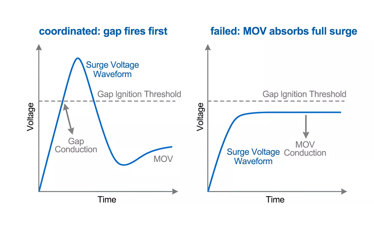
Figure 7 — Gap-to-MOV cascade timing — with adequate decoupling the gap fires first (left); without it the MOV conducts alone and the gap never ignites (right).
One design shortcut deserves mention before the mistakes section: if the panel cannot accommodate the separation or the inductor, a Type 1+2 combined device sidesteps the analysis entirely, because the internal coordination is factory-tested as an assembly under IEC 61643-11. The TRS8 pairs a gap stage with MOVs in one housing, rated Iimp 12.5kA with Up ≤1.5kV, and the internal coordination is verified under TUV Rheinland certification. For panel builders, that trades an engineering calculation for a catalogue selection.
Common SPD coordination mistakes in the field
Treating 10 meters as a guarantee. Cable length decouples the stages only if the device characteristics allow it. A crossed V-I curve pair stays crossed at any distance. Check the curves, or use devices from one manufacturer’s coordinated range.
Ignoring the cable route. The 10 meters that matter are conductor length, not straight-line distance between panels. A Type 1 and Type 2 mounted 12m apart but fed through a shared 2m busbar section have 2m of decoupling, not 12.
Skipping the third stage. A well-coordinated Type 1 and Type 2 pair can still deliver 1.0–1.5kV to equipment. Electronics with a 0.8kV withstand rating need a Type 3 SPD within a few meters of the load. We see this gap in roughly one in three retrofit projects: entrance and panel protection done correctly, then a VFD or PLC failure that traces back to the last unprotected meters.
Mixing manufacturers without checking energy data. The energy criterion needs each device’s maximum energy withstand, and datasheets from different suppliers rarely state it on a comparable basis. Within a single coordinated product line, the manufacturer has already run that analysis.
Forgetting the SCPD. Each SPD stage needs its own overcurrent protection, and the backup device’s let-through changes the surge path. SPD coordination analysis that stops at the SPDs is incomplete: the SPD wiring diagram for each stage has to include the disconnector.
FAQ
What is SPD coordination and why is it required?
SPD coordination is the matching of cascaded surge protective devices so each stage absorbs only the energy it is rated for. IEC 61643-12 clause 7.2.7 requires it because an uncoordinated downstream SPD can conduct first, absorb lightning-class energy on an 8/20µs rating, and fail, leaving equipment unprotected.
How do Type 1 and Type 2 SPDs divide the work in a cascade?
The Type 1 SPD diverts direct lightning current (10/350µs waveform) at the service entrance; the Type 2 SPD cuts residual and switching surges (8/20µs) to equipment-safe levels in the distribution board. Neither can substitute for the other. The cascade works because each covers what the other cannot. For a full breakdown of all three types, see our Type 1 vs Type 2 vs Type 3 SPD comparison.
What if 10 meters of cable between SPDs is not possible?
Install a decoupling inductor of around 10–20µH between the stages, or select a Type 1+2 combined SPD with factory-tested internal coordination. The 10m figure is informative guidance in IEC 61643-12, not a normative requirement. The actual requirement is energy coordination, which either method satisfies.
How many SPD stages does an installation need?
Two stages (Type 1 + Type 2) cover most industrial installations with an external lightning protection system or overhead supply. Add a Type 3 stage when equipment withstand voltage is below the Type 2’s protection level, typically for PLCs, VFDs, and control electronics. Buildings without LPS or overhead lines often need only Type 2 protection.
Thor Electric coordinated SPD ranges
Thor Electric manufactures Type 1, Type 2, and Type 1+2 combined SPDs as coordinated product lines, certified under IEC 61643-11 with TUV and CE approval. The TRS-A graphite gap series, TRS-B/C/D MOV series, and TRS8 combined devices cover cascade designs from service entrance to terminal equipment, with samples and OEM options available. Discuss your project requirements with our engineering team.