
How to size an SPD, or surge protection device, comes down to four numbers. A Type 1 SPD needs an impulse current Iimp that follows from the lightning protection level: 12.5 kA per pole for LPL III and IV, 25 kA for LPL I. A Type 2 SPD needs a nominal discharge current In of at least 5 kA per mode and a maximum discharge current Imax chosen by exposure, with 40 kA the usual main-board choice. The maximum continuous operating voltage Uc must be at least 1.1 times the line-to-neutral voltage, which means 275 V on a 230 V TN or TT supply. Finally, the voltage protection level Up, plus the voltage on the connecting leads, has to stay below the impulse withstand of the equipment you are protecting.
The rest of this page derives each number, then runs three real boards through the full SPD sizing method, from the kA rating to the model.
How to size an SPD: the four numbers
Each value is worked out in its own section below; for what each one means on a datasheet, see SPD parameters explained.
| Value | What sets it | Typical result at 230/400 V |
| Iimp (Type 1, 10/350 µs) | Lightning protection level and how the current splits | 12.5 kA per pole (LPL III/IV), 25 kA per pole (LPL I) |
| In and Imax (Type 2, 8/20 µs) | Standard minimum for In; site exposure for Imax | In ≥ 5 kA per mode; Imax 20, 40 or 65 kA and above |
| Uc | Earthing system and supply voltage | 275 V in TN and TT; 440 V or more in IT without neutral |
| Up | Equipment withstand Uw and the lead voltage | Up plus leads at or below 2.0 kV for ordinary equipment within 10 m |
Type comes first because it decides which current you size
You size Iimp only when the board needs a Type 1 SPD. That applies when the building has an external lightning protection system, or when an overhead supply line can carry part of a direct strike into the installation. Every other origin board gets a Type 2 SPD, and SPD sizing then works on In and Imax instead. If you are still deciding between the classes, the comparison of Type 1, Type 2 and Type 3 SPDs covers the choice; the rest of this page assumes it is made.
Type 1 SPD: calculating the impulse current rating
Iimp is the lightning current share each pole has to survive, and calculating the SPD rating for a Type 1 device is mostly arithmetic on how that current splits. IEC 62305 assigns each lightning protection level a maximum peak current for a direct flash: 200 kA for LPL I, 150 kA for LPL II and 100 kA for LPL III and IV. The working assumption is that half of that current flows into the earth termination and half leaves the building through its conductive services.
If the power supply is the only metallic service, the whole 50 % goes into the supply cable and divides among its conductors. A 230/400 V supply with three lines and a neutral has four conductors, so for LPL III/IV the sum is 100 kA × 0.5 ÷ 4 = 12.5 kA per pole. For LPL I it is 200 kA × 0.5 ÷ 4 = 25 kA. Figure 1 shows the split.
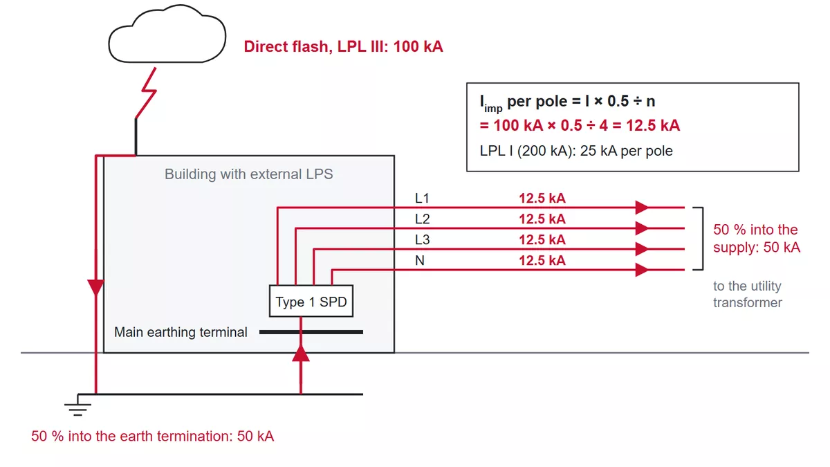
Figure 1 — How a 100 kA LPL III flash divides into 12.5 kA per pole at the supply SPD.
| Lightning protection level | Maximum flash current | Share into the supply (50 %) | *Iimp* per pole, four conductors |
| I | 200 kA | 100 kA | 25 kA |
| II | 150 kA | 75 kA | 18.75 kA |
| III and IV | 100 kA | 50 kA | 12.5 kA |
Two details change the result. First, a building with water, gas or data lines also entering it shares the 50 % across more paths, so each pole sees less. Treating the power cable as the only service is the conservative case, and it is the one most installers use. Second, in a 3+1 arrangement the single N-PE spark gap carries the current of all four conductors at once, so it needs 50 kA at the 12.5 kA level on a three-phase supply and 25 kA on a single-phase one.
When nobody has done a lightning risk assessment and no national rule says otherwise, IEC 60364-5-53 sets 12.5 kA per mode as the minimum for a Type 1 SPD. That is the figure most specifications quote, and the table above shows where it comes from.
Type 2 SPD: choosing the kA rating
In has a hard floor. A Type 2 SPD at the origin of the installation needs at least 5 kA (8/20 µs) per protection mode. In a 3+1 arrangement, the N-PE path again carries the sum: at least 20 kA on a three-phase supply and 10 kA on a single-phase one.
Imax is the kA rating most datasheets print largest, yet it has no minimum in the installation standard, which is why Type 2 SPDs are sold anywhere between 10 kA and 150 kA. The common engineering practice is to pick it by exposure:
| Exposure | Typical site | *Imax* per pole |
| Low | Urban or suburban building among others, underground supply | 20 kA |
| Medium | Building on open ground; the usual main-board choice | 40 kA |
| High | Overhead supply, hilltop, isolated tall structure, high flash density | 60–100 kA |
These bands are guidance, not a requirement. A higher Imax buys margin against a single large surge. If the site sees frequent repeated surges, compare In as well, because In is the rating the SPD is tested to take repeatedly in the operating duty test. Up is a separate SPD sizing step, two sections down.
Choosing Uc from the earthing system
Uc, the maximum continuous operating voltage, is the highest voltage the SPD can sit across continuously. IEC 60364-5-53 sets it at least 10 % above the normal voltage across each protection mode, and the earthing system decides what that normal voltage is. On a 230/400 V supply the answer is one of three values:
| Supply | *Uc* line to PE and line to neutral | Why |
| TN or TT, normal supply | 275 V | 1.1 × Uo = 1.1 × 230 V = 253 V; 275 V is the standard rating above it |
| TN or TT, supply that runs high | 320 V | Long rural feeders and weak grids can sit near 253 V for long periods |
| IT without a distributed neutral | 440 V or more | An earth fault puts the line voltage across the SPD: 1.1 × 400 V = 440 V |
The neutral-to-PE path in TN and TT needs only the 230 V supply voltage, so a 255 V N-PE module is enough.
Temporary overvoltage is a separate check. A fault on the supply side can hold the voltage above Uc for milliseconds to seconds, and the question then is whether the SPD’s tested UT and duration cover it, or whether the device fails safely. Raising Uc alone does not settle that.
Checking Up against equipment withstand
This is the step that most often sends SPD sizing back to the start. Up, the voltage protection level, is the voltage the SPD lets through. Every piece of equipment has an impulse withstand voltage Uw set by its overvoltage category, and IEC 60364-4-44 gives these values for a 230/400 V installation:
| Overvoltage category | Example equipment | *Uw* |
| IV | Meters, primary overcurrent devices at the origin | 6 kV |
| III | Distribution boards, switches, socket-outlets, fixed industrial equipment | 4 kV |
| II | Appliances, tools, ordinary current-using equipment | 2.5 kV |
| I | Sensitive electronics protected by external means | 1.5 kV |
Two things push the voltage at the equipment above the datasheet Up. The first is the connecting leads. Every metre of wire between the conductors, the SPD and the earth bar has about 1 µH of inductance, which adds roughly 1 kV per metre for an 8 kA 8/20 µs surge and more for larger currents, which is why the total lead length should stay within 0.5 m. Figure 2 shows how that adds onto the Up of an MOV-based SPD to give the effective protection level Up,f. The second is distance: on a cable run longer than about 10 m, the surge reflects and builds up at the far end.
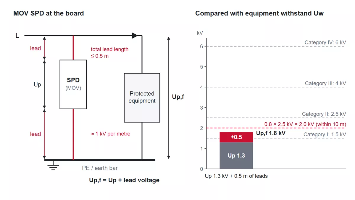
Figure 2 — For an MOV-based SPD, Up plus the lead voltage gives Up,f, which is compared with the Uw of each overvoltage category.
IEC 62305-4 turns that into two working rules:
- Equipment within about 10 m of the SPD: keep Up,f at or below 80 % of Uw. For ordinary Category II equipment, that is 2.0 kV.
- Equipment further away: either keep Up,f at or below half of Uw (1.25 kV for Category II), or put a second SPD close to the equipment. In practice the second SPD is usually the easier route.
When the first rule fails, shorten the leads or add a downstream SPD with a lower Up, coordinated with the first. That second stage is covered in coordinating a Type 1 and Type 2 cascade.
Worked examples: three boards sized end to end
Here are the same four SPD sizing steps applied to three different boards, all on a 230/400 V supply and all protecting Category II equipment:
| Step | A: office, TN-S, no LPS | B: factory, TN-C-S, LPS class III | C: LPL I structure, TN-S |
| SPD type | Type 2 at the main board | Type 1+2 at the origin | Type 1 at the origin |
| Current rating | Imax 40 kA (open site) | Iimp 12.5 kA per pole | Iimp 25 kA per pole |
| Uc | 275 V | 275 V | 275 V |
| Up check | Up,f 1.8 kV ≤ 2.0 kV (within 10 m): passes | Up,f 1.8 kV ≤ 2.0 kV (within 10 m): passes | Up,f 2.2 kV > 1.25 kV (15 m away): needs a second SPD |
| Result | TRS2-C40 4P | TRS5-B+C, 4P | TRS-A25 plus a Type 2 near the equipment |
Case A is a business-park office on open ground with an underground supply. Exposure is medium, so 40 kA Imax is the sensible choice, and in TN-S a four-pole 4+0 layout puts every conductor to PE. The Type 2 SPD TRS2-C40 in 4P form has In 20 kA, Imax 40 kA, Uc 275 V on every mode, and Up ≤ 1.3 kV. With 0.5 m of leads that becomes about 1.8 kV, under the 2.0 kV limit. Equipment more than 10 m away on floor boards gets its own SPD there, and the SPD sizing steps repeat for that board.
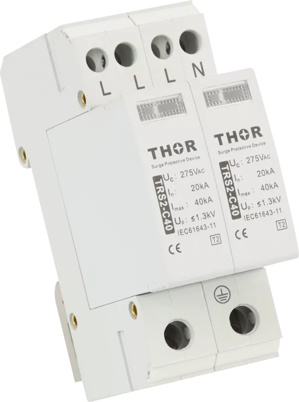
Figure 3 — Thor TRS2-C40 Type 2 SPD, four-pole, 275 V.
Case B has an external LPS designed to class III, so the origin needs 12.5 kA per pole. After the PEN split the board is TN-S, and a four-pole Type 1+2 SPD covers all four conductors. TRS5-B+C is rated for exactly this duty: Iimp 12.5 kA, In 20 kA, Imax 50 kA and Up ≤ 1.3 kV, so the same 1.8 kV result passes and one device does both the lightning-current and the surge job at the origin.
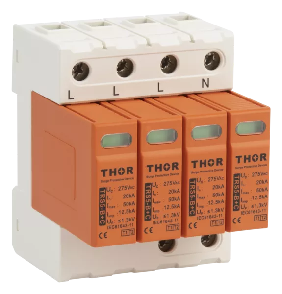
Figure 4 — Thor TRS5-B+C Type 1+2 SPD, four-pole.
Case C needs 25 kA per pole, which a spark-gap Type 1 SPD such as TRS-A25 matches. Its Up of ≤ 2.2 kV is high for Category II equipment, and that equipment sits 15 m away, past the 10 m point, where the target is half its Uw, 1.25 kV. The origin SPD cannot protect it alone. A coordinated Type 2 such as TRS-C40 (Up ≤ 1.3 kV) goes on the board close to it. For a spark gap, the lead voltage is not added to Up; the simplified method takes the larger of the two, so 2.2 kV is the figure either way. A spark gap also has one extra rating to check: its follow-current extinguishing capability Ifi must be at or above the prospective short-circuit current where it is installed, checked together with its backup protection. Confirm Ifi on the datasheet for the actual fault level before treating TRS-A25 as final.
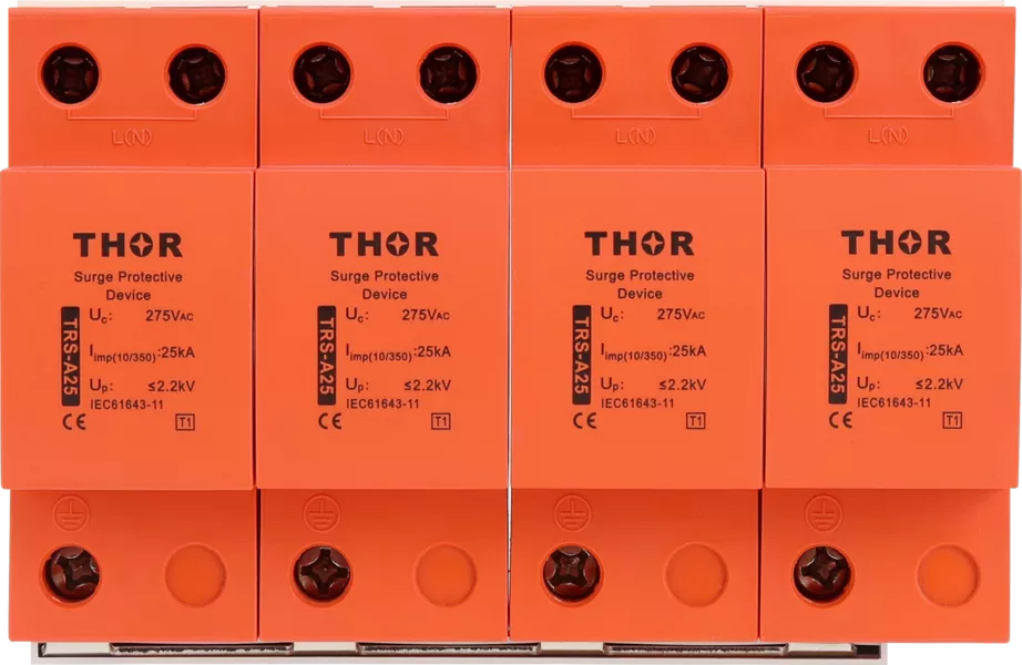
Figure 5 — Thor TRS-A25 Type 1 spark-gap SPD.
The last number in SPD sizing for any of these boards is the backup fuse or breaker, which depends on the SPD datasheet and the fault level; sizing the backup MCB or fuse walks through it.
FAQ
What size SPD do I need for a house?
For a house, the SPD size is usually set by the Type 2 rules. A typical house on a TN-C-S or TT supply with no lightning protection system needs a Type 2 SPD at the consumer unit: In at least 5 kA per mode, Imax 20 to 40 kA depending on exposure, and Uc 275 V. A TT supply needs a 1+1 or 3+1 layout with a separate N-PE path. A Type 1 SPD is only needed when the house has an external lightning protection system or an exposed overhead supply.
Is a higher kA rating always better on an SPD?
A higher Imax gives more margin against one large surge, which helps on exposed sites. It is not a blanket upgrade: on a sheltered urban board, 20 kA already covers the expected surges, and the extra rating adds cost. For sites with frequent repeated surges, compare In, the rating tied to repeated impulses, alongside Imax.
Why don’t DIN-rail SPDs have a joule rating?
Joule ratings belong to plug-in surge strips, where they give a rough, non-standardised idea of absorption capacity. IEC 61643-11 describes a DIN-rail SPD by its test class and current waveform (Iimp at 10/350 µs, In and Imax at 8/20 µs), its Uc and its Up. Those are the values SPD sizing works with, and they can be compared across manufacturers.
Getting the rating confirmed for your board
If you are specifying a surge protection device for a particular board, the four numbers above depend on a short list of facts: supply voltage and earthing system, whether there is an external LPS and its class, whether the supply arrives overhead or underground, where the board sits, and how far away the equipment it protects is. Send us those details and we will come back with the matching Thor model, its datasheet and the Up,f check for your layout.