
A surge protection device does not always announce its own failure beyond its local status indication. The metal oxide varistor (MOV) inside can degrade after a single large transient, or after years of smaller ones, while the panel continues energizing normally. Knowing how to test a surge protection device comes down to three things: reading the status indicator, using a multimeter only to screen for gross faults, and understanding what neither check confirms about the device’s remaining surge capacity. No routine field check replicates the impulse conditions used for SPD type testing under IEC 61643-11.
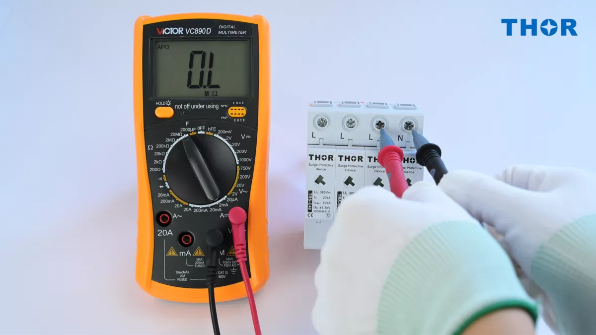
Figure 1 – A resistance-mode reading can screen for a gross fault, but it cannot confirm an SPD’s remaining surge capacity.
How to test a surge protection device: the short answer
Yes, but with a clear boundary. Field checks can identify a tripped internal disconnect, visible damage, or a gross electrical fault. The status indicator reports the cartridge’s local condition; it does not prove that every conductor is correctly connected. A multimeter can screen for a short circuit and support installation-level continuity checks, but it cannot measure clamping under a real transient. You are screening for faults, not auditing surge performance.
How to tell an SPD has failed: check the indicator first
Before reaching for any tool, look at the device. Thor pluggable SPD modules use visual fault indication. On the TRS-C40 shown here, green is the normal indication; a red fault area means the internal disconnect has operated and the cartridge needs replacing. The window reports the cartridge mechanism directly, but it does not verify external wiring or protective-conductor continuity.
For panels that are not inspected daily, an optional potential-free remote signaling contact (rated 250V/0.5A AC and 250V/0.1A DC) can report the change of state to a compatible BMS or SCADA input. The monitoring circuit and input rating still have to match the selected SPD and control system. Thor’s pluggable AC surge protection devices are available with this remote indication option.
Other physical signs worth a visual check: discoloration or bulging on the module housing, a burnt smell near the enclosure, or a breaker that has tripped without an obvious external cause. Any of these calls for replacement regardless of what an indicator shows.
Figure 2 shows the normal and fault states side by side on a Thor TRS4-C40 assembly.
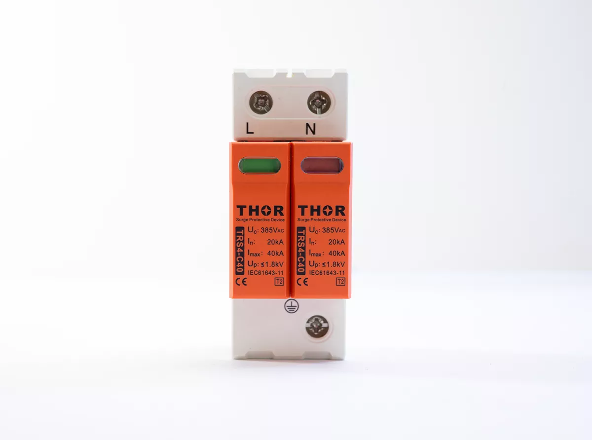
Figure 2 – Green normal indication and red fault indication on a Thor TRS4-C40 SPD.
Testing an SPD with a multimeter, and its limits
Moving beyond the indicator window to test an SPD with a meter, a multimeter is the next tool. Two things it can confirm:
- Resistance screening. Isolate and disconnect the SPD according to the manufacturer’s instructions before measuring. Across an MOV protection path, a low-voltage meter commonly shows high resistance or `OL`; a stable near-zero reading suggests a short-circuit fault. Terminal arrangements differ, so use the model’s wiring diagram rather than assuming the same probe points on every SPD. The metal oxide varistor (MOV) only begins conducting strongly above its voltage-dependent threshold.
- Protective-conductor continuity. Check the installation’s protective path with the SPD isolated as required by the test procedure. This is a wiring and bonding check, not a measurement of the MOV’s remaining surge capacity.
Here’s the catch a high reading hides: it only rules out a shorted MOV. A varistor that has degraded but hasn’t yet failed short reads high too. A “normal” resistance result tells you the device isn’t dead, not that it still has surge capacity in reserve.
The real limit, and where many field guides overstate what the tool can do: a multimeter cannot verify remaining surge-handling capacity. That verification only happens through impulse testing during manufacturing, per IEC 61643-11. Treat a clean multimeter reading as “no gross fault found,” not as “protection confirmed.”
Figure 3 separates the field checks a multimeter supports from the impulse behavior it cannot measure.
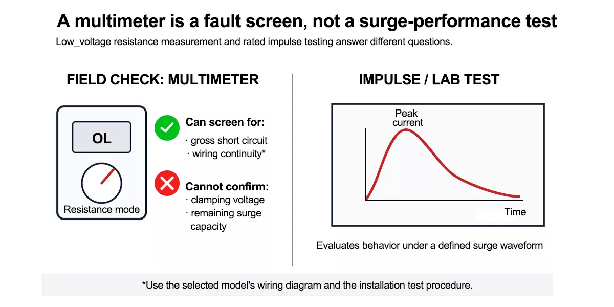
Figure 3 – A multimeter screens for gross faults; impulse equipment evaluates surge behavior under rated waveforms.
| Test Method | What It Confirms | What It Doesn’t | Tools Needed |
| Visual/remote indicator | MOV has tripped its internal disconnect | Root cause, remaining life of other modules | None (built-in) |
| Multimeter resistance screening | A gross short-circuit indication under the stated test setup | Remaining surge-handling capacity; correct external wiring | Digital multimeter |
| Insulation resistance (installation-level) | Overall circuit insulation integrity | SPD condition; SPD must be isolated first | Insulation resistance tester |
| Impulse/type testing | Full clamping performance under rated surge | — (manufacturer-only, not field-applicable) | Impulse test equipment (factory) |
The insulation resistance test: isolate the SPD first
The insulation resistance test sequence is the step most SPD testing guides get backward. An insulation resistance test (using a megger at 500V or 1000V) is meant to check the wiring and equipment insulation of the installation, not the SPD itself. Applying that test voltage across an installed MOV-based SPD pushes it past its clamping threshold, so the varistor conducts during the test. The result isn’t a low insulation reading because of a wiring fault; it’s the SPD doing exactly what it’s designed to do, distorting the measurement.
The correct sequence, in line with IEC 60364-6 installation verification practice: disconnect or isolate the SPD from the circuit before running the insulation resistance test, then reconnect it afterward. Some field guides suggest simply dropping the test voltage to 250V as a shortcut — that’s a common workaround, not a standard requirement, and it doesn’t reliably stop MOV conduction on every device. Isolating the SPD is the practice that actually holds up.
Figure 4 shows the sequence without implying that the diagram replaces the site’s isolation and lockout procedure.
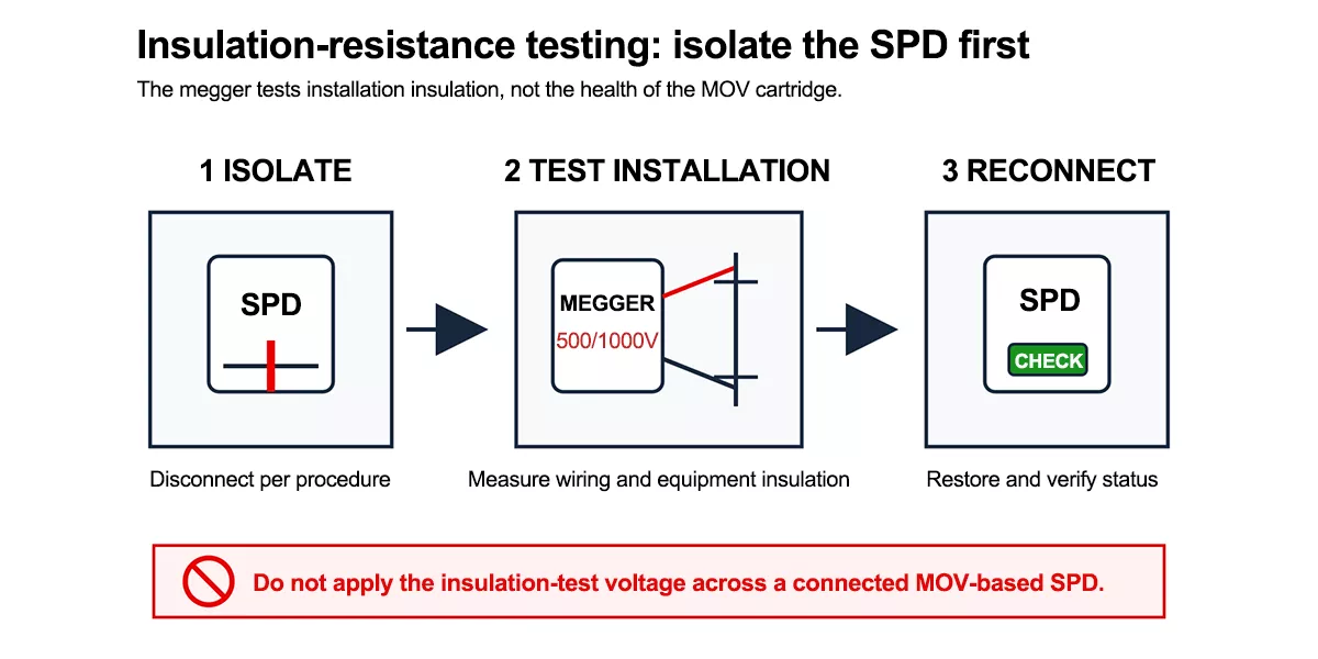
Figure 4 – Isolate the SPD, test the installation insulation, then reconnect the SPD and verify its status.
For a device-level health check beyond gross fault detection, manufacturers characterize MOV condition using the varistor’s U1mA reference voltage: the voltage at which the MOV starts conducting 1mA of current. A significant drop from the datasheet value signals aging. A DC varistor tester performs this measurement; it is a manufacturer or lab diagnostic, not something performed during routine field maintenance.
When to test, and when to replace
Knowing when to test surge protection is as important as knowing how. Test at minimum after any of these events:
- Following a lightning storm or a known regional surge event
- After a breaker trip with no other obvious cause
- At the interval specified by the manufacturer and the site’s maintenance plan; high-exposure locations normally justify more frequent inspection
Replacement does not wait for a reassuring meter reading. A red fault indication, visible module damage, or a manufacturer instruction to replace after a documented event takes priority over a low-voltage resistance result. Thor’s pluggable module design allows cartridge replacement without rewiring the base, but the applicable isolation and electrical-safety procedure still applies.
For the full picture on inspection intervals, wear indicators, and replacement timing, see the SPD maintenance guide. If the SPD in question has been in service for several years, the guide to SPD aging and end-of-life safety covers what drives degradation even without a single major surge event.
FAQ
How to test an SPD with a multimeter?
Use a multimeter only to screen for gross faults. Isolate and disconnect the SPD according to its instructions, select resistance mode, and use the probe points shown for that model. High resistance or `OL` can rule out an obvious short under that setup, but it cannot confirm remaining surge capacity; a stable near-zero reading calls for the device to remain out of service pending replacement or manufacturer guidance.
How do you know if an SPD is faulty?
The fastest indicator is the module’s built-in status window: on the model shown here, green is normal and red means the internal disconnect has operated. Physical signs like discoloration, bulging, or a burnt smell also call for replacement. Where fitted, an optional remote signaling contact can pass the status change to a compatible BMS or SCADA input.
What does an insulation resistance test actually measure on an SPD circuit?
It measures the wiring and equipment insulation of the installation, not the SPD. Running a megger across an installed MOV-based SPD pushes it past its clamping threshold, so the varistor conducts and the reading drops. The SPD must be isolated before the test; otherwise the result reflects the SPD doing its job, not a wiring fault.
How long does a surge protection device last?
Most industrial SPDs are rated for several years of service, but lifespan depends heavily on surge exposure rather than calendar time. A device in a high-lightning region or one that absorbs a major transient early can reach end-of-life much sooner than a low-exposure installation.
How often should SPDs be tested?
Check the status indicator during routine panel inspections and after a suspected surge event or unexplained breaker trip. Follow the manufacturer’s interval and the site’s risk-based maintenance plan; locations with frequent lightning or critical loads normally require more frequent checks.
Thor Electric SPDs
If field checks cannot quantify remaining surge capacity, clear condition indication becomes important. Thor’s pluggable SPD ranges include visual fault indication and are available with a potential-free remote signaling option; certifications and configurations should be verified for the selected model. Samples, custom Uc configurations, and OEM/ODM production are available. Discuss your project requirements