Do Solar Panels Need Surge Protection?
Yes — and in most grid-connected PV installations, a single surge event is enough to destroy the inverter. Solar panels themselves handle transient overvoltages reasonably well. The inverter, charge controller, and monitoring equipment connected to them do not — and replacing a failed inverter typically costs 10–20 times more than the surge protection device for solar panel that would have prevented the failure.
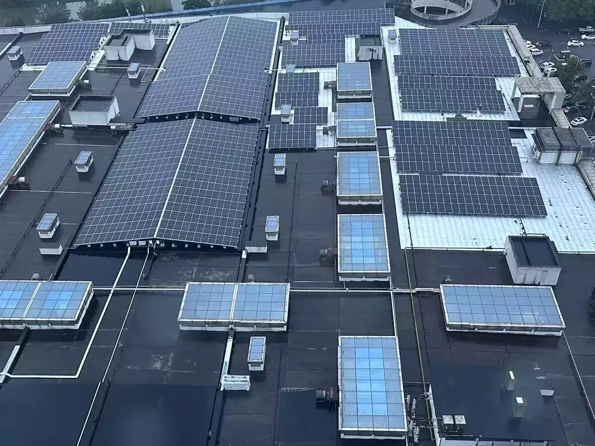
Figure 1 — PV plant overview showing combiner boxes and inverter cabinets
PV systems face surge exposure from two directions simultaneously. On the DC side, string cables running 100–300 metres across open ground act as antennas for lightning-induced electromagnetic pulses. A nearby strike — not even a direct hit — can induce transient voltages well above the inverter’s impulse withstand level. On the AC side, switching operations on the utility grid inject conducted transients back through the inverter. Most string inverters have no galvanic isolation between DC and AC circuits, so both sides need independent protection.
IEC 61643-31, the governing standard for SPDs in photovoltaic power systems, recognises this dual exposure and requires protection to be evaluated at both the DC array side and the AC output side of the inverter.
This is why selecting the right surge protection device for solar is not an afterthought — it is a design requirement from day one.
How Surges Enter a PV System
AC-side: grid switching and conducted transients
Every switching operation on the distribution network — transformer energisation, capacitor bank switching, fault clearance — generates a conducted transient that travels along the supply cables into the inverter’s AC terminals. A more severe threat is indirect lightning: a strike several kilometres away can couple into the distribution network and arrive at the inverter AC input with peak voltage still exceeding 2–4 kV — above the impulse withstand level of most inverter AC input stages, rated at 1.5–2.5 kV per IEC 60664-1 Category III.
DC-side: direct strike induction and long cable exposure
String cables connecting solar panels to the inverter DC input typically run 100–300 metres across open ground, unshielded, at heights of 0.5–1 metre above the surface. This geometry makes them highly effective antennas for lightning-induced electromagnetic pulses. When selecting a DC SPD, ensure the Ucpv rating is at least 20% higher than the array’s open-circuit voltage (Uocstc) to account for temperature fluctuations at low ambient temperatures.
A direct strike to the array or its surroundings produces far higher energy: the 10/350 µs waveform defined in IEC 62305 contains approximately 20 times more energy than the 8/20 µs waveform used to test standard Type 2 SPDs. This is why ground-mount systems in high keraunic zones — areas with more than 25 thunderstorm days per year — require Type 1 or Type 1+2 SPDs on the DC side. Specifying the correct surge protection device for solar panel in these zones is a project requirement, not an option.
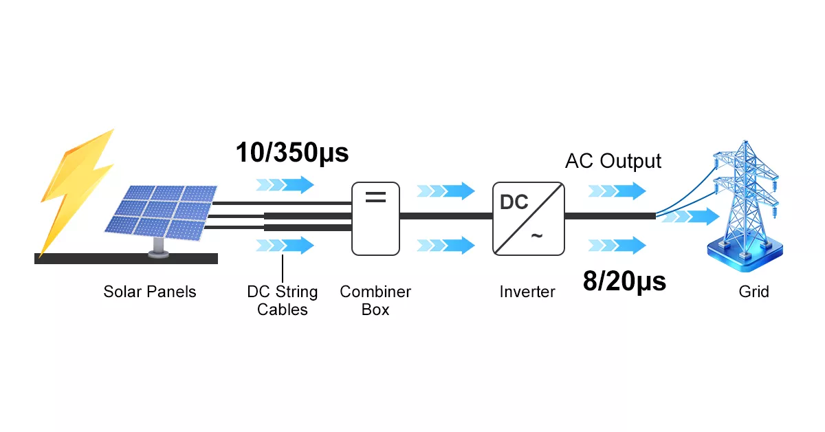
Figure 2 — Lightning surge induction path in a solar PV system: DC side (10/350µs) and AC side (8/20µs)
Where to Install a Surge Protection Device in a Solar System
A PV system requires SPD protection at two independent points. Installing at only one location leaves the other exposed — a surge entering the DC string cables can propagate through the inverter and appear on the AC output, and vice versa.
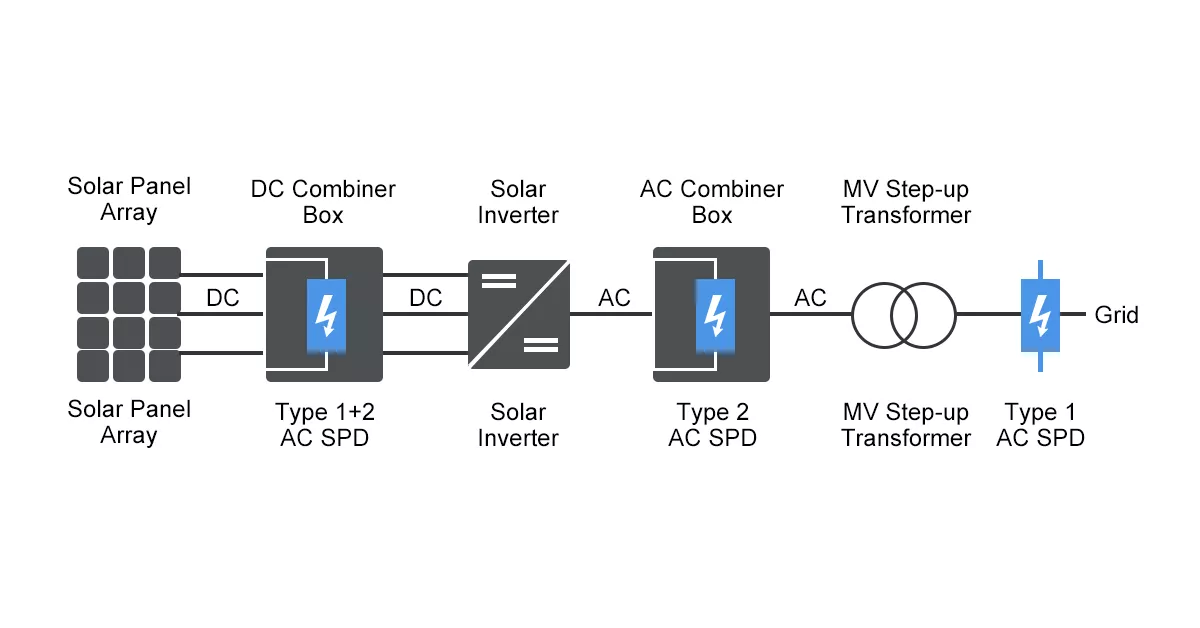
Figure 3 — SPD installation positions in a solar PV system: Type 1+2 PV SPD at DC combiner box, Type 2 AC SPD at AC distribution board, and Type 1 AC SPD at MV transformer secondary
DC combiner box — first line of defence
The primary DC-side installation point is the combiner box, positioned between the PV string cables and the inverter DC input. For rooftop systems without an external LPS, a Type 2 PV SPD is standard. Thor’s TRS3-C40 covers Ucpv from 600V to 1500V DC, with In 20kA and Imax 40kA, certified to IEC 61643-31. For ground-mount installations in high keraunic zones, a Type 1+2 PV SPD is required — the TRS3-C40 High Module variant handles Iimp of 7kA at 1000V and 5kA at 1500V DC systems.
Keep total lead length below 0.5 metres. Each additional metre adds approximately 1µH of inductance — at a rise rate of 10kA/µs, that translates to 10kV of additional voltage that negates the SPD’s rated Up.
Inverter AC output — second line of defence
The AC-side SPD is installed at the inverter’s AC output terminals. For most residential and commercial PV systems, Thor’s TRS4-C40 Type 2 AC SPD provides In 20kA and Imax 40kA with Up ≤1.3kV, certified to IEC 61643-11. Where the main distribution board is exposed to direct strike risk, upgrade to the TRS5-B+C Type 1+2, which delivers Iimp 12.5kA and Up ≤1.3kV.
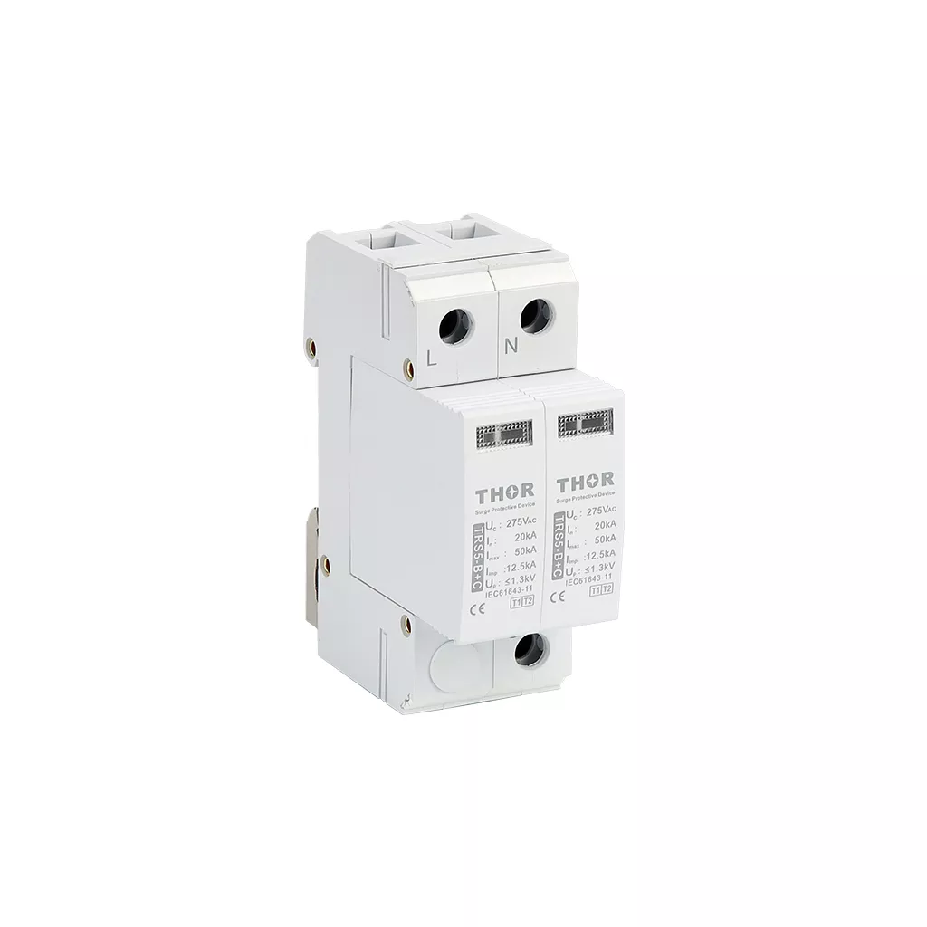
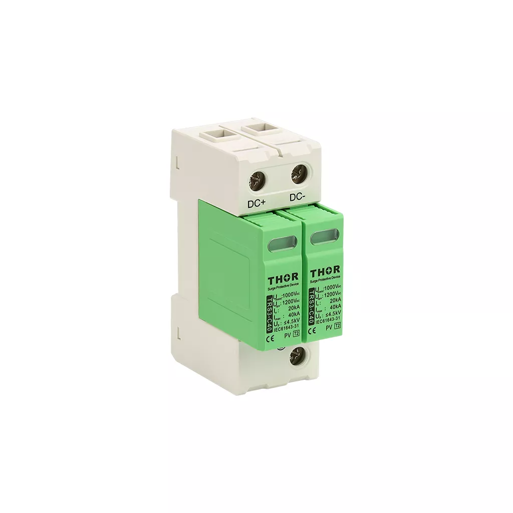
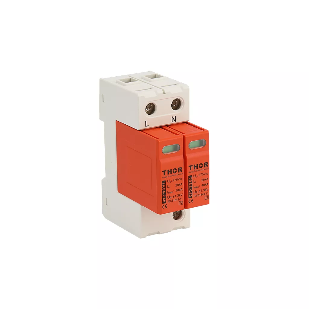
Figure 4 – Thor TRS3-C40 PV SPD (DC side), TRS4-C40 Type 2 AC SPD, and TRS5-B+C Type 1+2 AC SPD for single phase solar panel system protection
Alt text:Thor TRS3-C40 PV SPD TRS4-C40 and TRS5-B+C AC surge protection device for solar panel system
Type 1 vs Type 2 SPD for Solar: Which Do You Need?
The distinction between Type 1 and Type 2 is not a quality ranking — it is a classification based on installation position and the surge energy each device is designed to handle.
| Type 1 | Type 2 | Type 1+2 | |
| Test waveform | 10/350µs | 8/20µs | Both |
| Key parameter | Iimp | Imax | Iimp + Imax |
| Energy level | Direct lightning | Conducted/induced | Both |
| Typical position | Service entrance, LPS present | Distribution board, no LPS | Ground-mount, high keraunic zones |
| IEC standard | 61643-11 Class I | 61643-11 Class II | 61643-11 T1+T2 |
The 10/350µs waveform used to test Type 1 devices contains approximately 20 times more energy than the 8/20µs waveform at the same peak current. A Type 2 SPD exposed to direct lightning strike current will fail — not because it is a lower-quality product, but because it was never designed for that energy level.
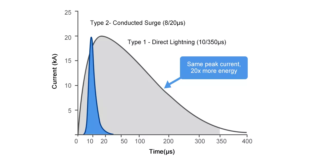
Figure 5 — 10/350µs vs 8/20µs waveform comparison: same peak current, Type 1 carries approximately 20 times more energy than Type 2
Scenario guide:
- Rooftop residential or commercial, no external LPS — Type 2 PV SPD on DC side, Type 2 AC SPD on inverter output. Standard configuration for the majority of installations.
- Ground-mount in high keraunic zone (Ng > 25 strikes/km²/year) — Type 1+2 PV SPD on DC combiner box, Type 1+2 AC SPD at main board.
- Any system with an external lightning protection system connected — Type 1+2 required at the LPS earth connection point per IEC 62305 risk assessment.
Key Parameters When Selecting a PV Surge Protection Device
Maximum continuous operating voltage (Uc)
Uc is the highest voltage an SPD can sustain indefinitely without conducting. Select below this threshold and the SPD activates under normal operating voltage, overheats, and fails within months.
For PV DC systems, the correct calculation is:
Ucpv ≥ 1.1 × Voc(STC) × temperature correction factor
Voc(STC) is the string open-circuit voltage at 25°C. The 1.1 multiplier provides a minimum 10% margin. The temperature correction factor accounts for cold-weather conditions — silicon cells produce higher Voc as temperature drops, meaning a string measuring 1000V at 25°C may reach 1100–1150V on a cold winter morning.
For a 1000V DC system: Ucpv ≥ 1100V — the TRS3-C40 specifies Ucpv = 1200V DC, providing adequate margin. For a 1500V DC system: Ucpv ≥ 1650V.
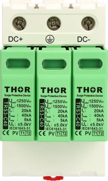
Figure 6 – TRS3-C40 Type 1+2 PV SPD specification label showing Ucpv 1250V, Uc 1500V, In 20kA, Imax 40kA, Iimp 5kA, Up ≤5.0kV, certified to IEC 61643-31
Nominal and maximum discharge current (In / Imax)
In is the discharge current the SPD handles repeatedly without degradation (15 impulse test). Imax is the single-event maximum. For Type 2 PV surge protection devices, In 20kA and Imax 40kA covers most commercial and industrial PV installations. When comparing products, verify these values are tested to IEC 61643-31 — the standard specifically written for surge protection device for solar panel and PV system applications.
Voltage protection level (Up)
Up is the residual voltage across the SPD terminals during a surge — the voltage that reaches the protected equipment. It must be lower than the impulse withstand voltage of the inverter’s DC input stage, typically 4–6kV for modern string inverters. The practical target for 1000V DC systems is Up ≤ 4.5kV.
Three Installation Mistakes That Defeat Your SPD
Lead length exceeding 0.5 metres
Every metre of conductor between SPD terminals and the protected circuit adds approximately 1µH of parasitic inductance. At a lightning current rise rate of 10kA/µs, that generates 10kV of additional voltage on top of the SPD’s rated Up. An SPD specified at Up ≤ 4.5kV with 1 metre of lead wire effectively delivers 14.5kV to the inverter input. Keep total lead length — line plus earth conductor combined — below 0.5 metres.
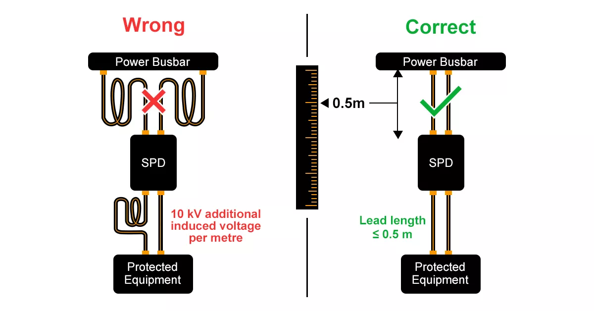
Figure 7— Correct vs incorrect SPD lead length installation comparison
Missing or high-impedance earth bonding
An SPD diverts surge current to earth. If the earth conductor has high impedance — long run, undersized conductor, or poor connection — the surge voltage appears across the load regardless of whether the SPD operated correctly. Earth conductors must be sized at minimum 4mm² copper for Type 2 and 16mm² for Type 1. All SPDs, the inverter, and the combiner box must share a common equipotential bonding point. This applies to every surge protection device for solar panel regardless of system size.
No overcurrent protective device in series
MOV-based SPDs have two failure modes: open-circuit (safe) and short-circuit (not safe). Without a fuse or circuit breaker in series, a short-circuit failure creates a permanent short across the supply with fire risk. IEC 61643-11 requires a backup OCPD for all SPD installations. For Thor’s TRS3 series, the recommended backup is a 63A gG fuse.
Solar SPD Selection: Quick Checklist
Use this checklist before finalising any surge protection device for solar panel specification.
Product selection:
- DC-side SPD type confirmed — Type 2 for rooftop without LPS, Type 1+2 for ground-mount or high keraunic zones
- AC-side SPD type confirmed — matches inverter output voltage and system exposure
- Ucpv ≥ 1.1 × Voc(STC) × temperature correction factor
- Up below inverter impulse withstand voltage
- Backup overcurrent protective device specified and sized
Installation:
- DC SPD installed at combiner box
- AC SPD installed at inverter AC output, before main distribution board
- Total lead length confirmed below 0.5 metres
- All SPDs bonded to common equipotential earth bar
- Earth conductor sized at minimum 4mm² (Type 2) or 16mm² (Type 1)
Compliance:
- DC-side SPD certified to IEC 61643-31
- AC-side SPD certified to IEC 61643-11
- IEC 62305 lightning risk assessment completed for ground-mount systems
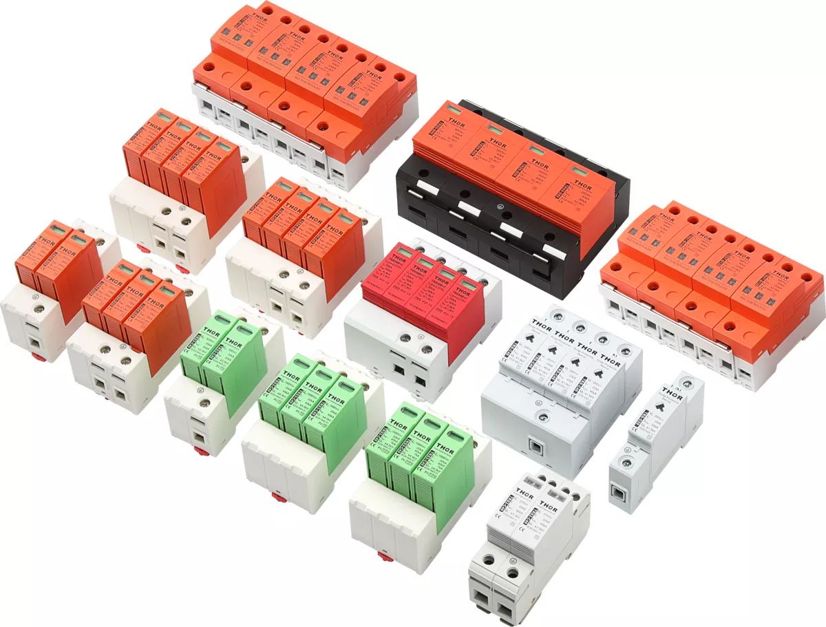
Figure 8 – Thor Electric PV and AC surge protection device product range, IEC and TUV certified
Thor Electric’s PV surge protection devices cover DC system voltages from 600V to 1500V, with Type 2 and Type 1+2 variants certified to IEC 61643-31. For AC-side protection, the AC surge protection device range includes Type 2 and Type 1+2 options for single-phase and three-phase inverter outputs.
For project-specific SPD specifications or bulk procurement inquiries, contact the Thor Electric team