
When a relay, contactor or solenoid switches off, the energy stored in its magnetic field drives the voltage up until the current finds somewhere to go. On an unsuppressed 24 V DC coil, that spike can reach several hundred volts across the contact or transistor that opened the circuit. Inside a control panel, this is the most common source of switching surges.
Switching surge protection in a panel works at two points. A suppressor across each coil stops the spike where it starts. An SPD at the incoming supply limits the switching transients that arrive from outside the panel, from motors, capacitor banks and network switching elsewhere on the site. A coil spike on a 24 V control circuit never reaches the incomer SPD, so each device has its own job.
How a switching surge develops
A contactor coil builds a magnetic field while current flows through it. That field pulls in the armature and stores energy. When the control output opens, the current starts to fall and the field collapses. The collapsing field generates a voltage that tries to keep the current flowing in its original direction.
The faster the current is forced to stop, the higher that voltage climbs. With no path for the current, it rises across the opening contact or output transistor until something breaks down: the air gap arcs, or the transistor goes into avalanche. Contact arcing and wiring capacitance add fast oscillations on top. A suppressor across the coil gives the current a controlled path so the stored energy dissipates there instead. Texas Instruments walks through this process in its inductive-load discharge application brief.
Figure 1 shows the simplest DC case. With the output on, the supply energizes the coil and the diode blocks. When the output opens, the coil current carries on around the local loop through the diode until the field has decayed.
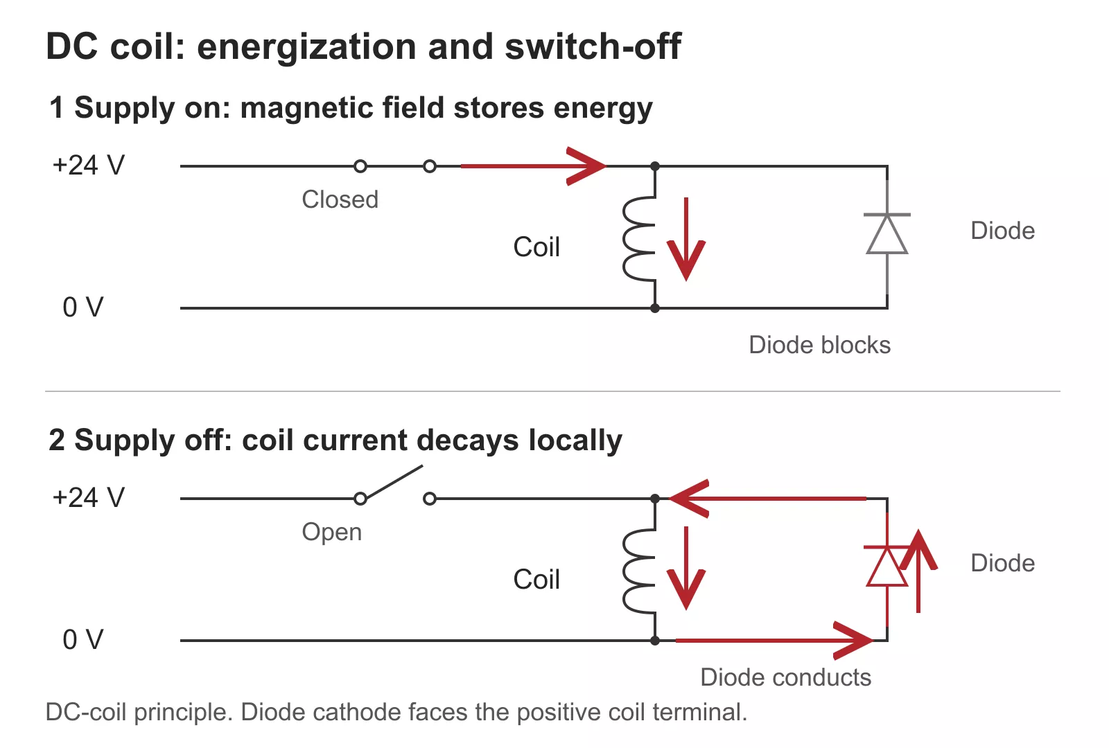
Figure 1 — A flyback diode gives DC coil current a local path during switch-off.
Larger switching events come from the power side. Energizing a capacitor bank sets up an oscillation with the supply inductance. Transformer energizing, large motor starts and circuit-breaker operations create transients on the distribution network. These arrive at the panel on the supply conductors, and they are what the panel SPD is there for.
How the disturbance reaches other equipment
A switching transient travels along shared supply and return conductors. Every conductor has some impedance, so a fast current change on one circuit becomes a voltage step for every other circuit sharing that conductor. Cables run side by side in the same duct also couple capacitively and inductively, which is how a contactor’s power wiring disturbs the analogue signal running next to it.
What the receiving equipment does depends on the level. A large spike can stress a PLC input or destroy an output driver. A smaller one can flip a digital input or upset an analogue reading. Short suppressor connections at the source, plus separation between power and signal wiring, cut the disturbance at both ends of the route.
A controller that resets when a motor starts may be seeing a supply dip instead of a transient. Motor inrush can pull the supply down for tens of milliseconds, while a switching transient lasts microseconds. They need different fixes, so capture the voltage during the event before buying anything.
Choose suppression for the switching source
For a relay or contactor, start with the manufacturer’s own suppression module or a coil version with suppression built in. The module is matched to the coil voltage and its effect on release time is already known. If you fit an external suppressor, connect it right at the coil terminals with short leads.
The coil supply and how fast the contacts must open decide the type:
| Coil or application | Suppression | What to check |
| DC coil, slower release acceptable | Flyback diode across the coil | Polarity, plus diode current and reverse-voltage ratings |
| DC coil, fast release needed | Diode with Zener, or a TVS diode | Clamping voltage below the driver’s rating; measured release time |
| AC coil | Varistor or RC suppressor | AC voltage rating, energy rating, manufacturer compatibility |
| Contactor with an accessory socket | Matching suppression module | Coil code and voltage range |
A plain flyback diode holds the reverse voltage at about 1 V, so the coil current decays slowly. The contactor can take several times its normal drop-out time to release. A diode-Zener combination or a TVS clamps at a higher voltage, so the energy dissipates faster and the contacts open sooner. Keep that clamp voltage below the rating of the transistor or contact driving the coil.
Release time matters most on brakes, interlocks and safety circuits. Use a diode-Zener or varistor there, then measure the drop-out time against the machine’s requirements. Omron’s relay precautions and TE Connectivity’s DC relay suppression guidance both show how each suppressor type changes release dynamics and contact life.
AC coils need an AC suppressor; a diode would short the coil on every half-cycle. A varistor clamps by conducting hard above its rated voltage, as the MOV explanation describes. An RC suppressor, a resistor and capacitor in series, absorbs the energy and slows the voltage rise. Size either one for the coil voltage and how often the contactor switches.
Add SPD protection to exposed supply circuits
The panel SPD sits at the incoming supply, connected between the line conductors and PE. It clamps transients that arrive on the supply: lightning-induced surges and the network switching events described above. The coil suppressor handles the energy the panel creates itself. Figure 2 shows the two side by side.
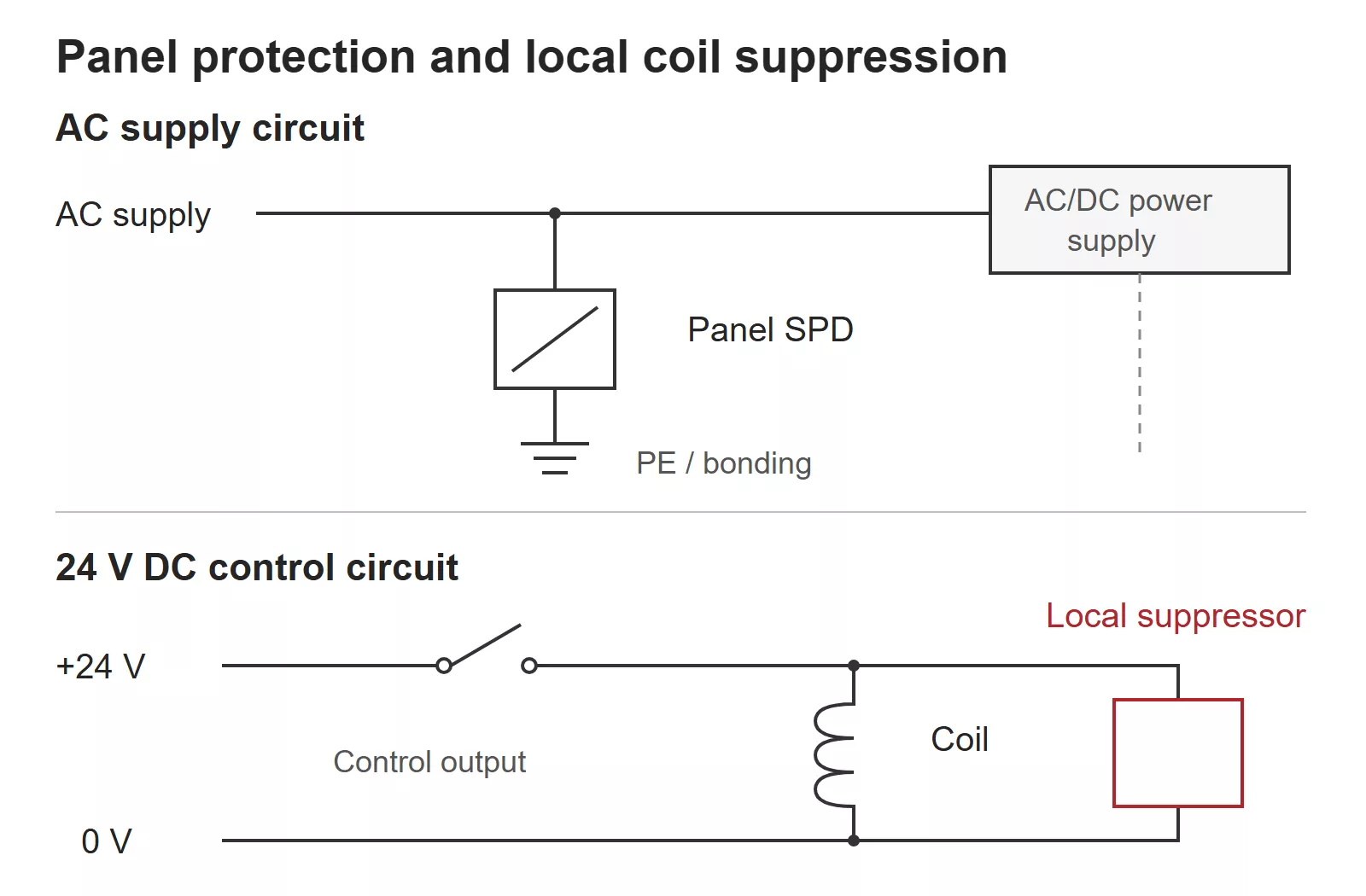
Figure 2 — A panel SPD protects the AC supply circuit while a local suppressor acts across the DC coil.
For a 230/400 V TN distribution board, the usual choice is a Type 2 SPD with Uc of 275 V. Check its voltage protection level, Up, against the withstand of the electronics it protects, then confirm the surge rating and backup fuse. The SPD sizing guide covers those checks.
The 24 V DC control circuit needs its own DC SPD when its cables leave the panel, for example to field sensors, outdoor equipment or another building. Long external runs pick up induced surges that the AC SPD never sees. Keep SPD leads short and follow the manufacturer’s layout; the SPD wiring diagrams show the usual parallel connection. Variable-speed drives are a separate case: protect the PWM motor output with the drive maker’s filters or chokes and keep the SPD on the drive’s supply side.
Check the result during normal switching
Test the fix with the machine running its normal sequence:
- Note which contactor, relay or load is switching when the fault happens, and whether it happens at switch-on or switch-off.
- Check the coil voltage and any built-in suppression, then confirm the added suppressor’s rating, polarity and terminals.
- Capture the affected supply or signal during the event with an oscilloscope and probes rated for the circuit voltage. A spike lasting microseconds points to switching; a sag lasting tens of milliseconds points to a supply dip.
- Run the switching sequence again after the change. The controller should stay up, and relay or contactor release times, including those on interlocks, should still meet the machine’s requirements.