
A TN-C earthing system, often typed TNC, uses one conductor, the PEN, as both the neutral and the protective earth, all the way from the transformer to the equipment. That saves a conductor and gives a low-impedance path for fault current, but it costs three things: RCDs cannot protect a TN-C circuit, part of the neutral current flows through bonded metalwork, and a broken PEN can make equipment enclosures live.
TN-C is normal in distribution networks and still common in older buildings. Inside an installation, the practical answer is to split the PEN at the main board and run TN-C-S from there. Where the PEN is still combined, an SPD connects 3+0, from each line to the PEN, rated Uc 275 V or higher on a 230/400 V supply.
How a TN-C earthing system works
The three letters describe the whole arrangement. T: the source neutral is connected directly to earth at the transformer. N: exposed metal parts of the installation are connected back to that earthed neutral. C: the neutral and the protective function share a single conductor, combined through the whole system.
That combined conductor is the PEN, and it has two jobs at once. In normal operation it carries the return current of every single-phase load and the unbalance of the three-phase loads, exactly like a neutral. It is also the conductor that every equipment enclosure is bonded to, exactly like a PE.
When a line conductor touches an enclosure, the fault current runs from the line, into the enclosure, along the PEN and back to the transformer star point. The whole loop is metal, so its impedance is low and the fault current is high, usually hundreds or thousands of amps. A fuse or circuit breaker sees that as an overcurrent and disconnects quickly. Until it does, the enclosure sits at a large fraction of the line-to-earth voltage, roughly half of it when the PEN and the line conductor are the same size, because the fault current divides the voltage between them.
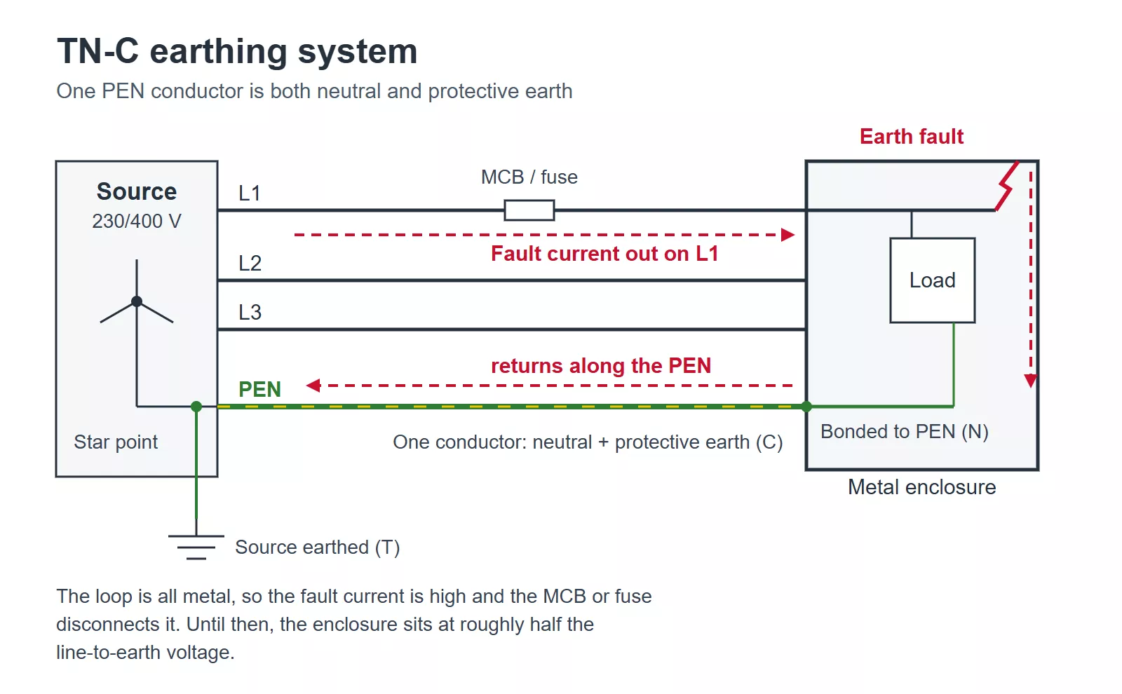
Figure 1 — TN-C earthing system: one PEN conductor is both neutral and protective earth, and an earth fault returns along it to the transformer.
The dual job also explains the rules a PEN must follow. It carries load current that a protective conductor never should, so a break anywhere along it removes the earth from everything downstream. IEC 60364-5-54 therefore allows a PEN only in fixed wiring and sets a minimum size of 10 mm² copper or 16 mm² aluminium, for mechanical strength. A PEN must never pass through a switch, isolator or fuse, because opening it would disconnect the protective earth while the line conductors may stay live. And a PEN is insulated for the full working voltage, because it is a current-carrying conductor that happens to also be the earth.
One consequence is easy to miss. Because the PEN carries load current, there is a voltage drop along it, and every enclosure bonded to it sits a few volts above true earth in normal operation. On a heavily loaded or unbalanced feeder that offset can be large enough to feel as a tingle between an appliance and a radiator, without any fault being present.
Where TN-C is still used
Most low-voltage distribution networks are TN-C. The cable from the substation to a street or building carries three lines and a PEN, and that PEN is earthed at the transformer and often at further points along the route. A building supplied this way becomes TN-C-S at the point where the PEN is split into separate neutral and earth.
The UK is the clearest example. Network operators run their cables as TN-C and earth the PEN at many points, a practice called protective multiple earthing (PME), then split it at the consumer’s cut-out. Regulations in Great Britain do not allow a PEN inside a consumer’s installation, so a UK reader who meets “TN-C” on a drawing or a forum is almost always looking at a PME supply, which is a TN-C-S earthing system on the consumer’s side. The overview of earthing system types covers where the GB prohibition comes from.
Inside installations, TN-C survives in two places:
- Older buildings wired when four-wire distribution was the norm: large parts of the former Soviet Union and Eastern Europe, older German installations built under the classic Nullung practice, and older housing stock in many markets that followed the same model. Typically the building risers are TN-C and the flats are wired with two conductors. Depending on the era and the country, the second conductor is either a neutral with no protective connection anywhere, or a small PEN with the socket earths bridged to it under the rules of the time. The two look the same in the box, so test before assuming either.
- Industrial plants with large four-wire feeders, where the PEN is well above the minimum size and the loads are mostly three-phase motors with little neutral current.
New installations rarely use TN-C beyond the origin. The reasons are in the next section.
What one conductor for neutral and earth costs you
Every drawback of a TN-C earthing system comes from the PEN doing two jobs. Three of them matter in practice.
RCDs cannot protect a TN-C circuit
An RCD compares the current going out on the live conductors with the current coming back, and trips when the difference shows that some current has leaked to earth. That only works if the leakage returns by a path outside the RCD. In TN-C, the earth path is the PEN, and the PEN has to pass through the RCD because it is also the neutral. Fault current that leaves on the line conductor comes back on the PEN, through the same core, and the two cancel. The RCD sees little or no difference and cannot give the protection it is installed for. Part of the fault current may return through pipework or the ground and trip it occasionally, but that is luck, not protection.
IEC 60364-4-41 does not allow RCDs in TN-C for this reason. The practical effect is that a TN-C circuit has no additional protection against electric shock and no RCD protection against earth-fault fires, which is the main reason modern wiring rules push installations toward a separate protective conductor.
A broken PEN makes enclosures live
If the PEN breaks, every enclosure downstream loses its earth and stays connected to a conductor that now floats. Load current trying to return through the break pulls the floating PEN toward line voltage, so a metal appliance case can become live without any fault in the appliance and without enough current to blow a fuse. The earthing types overview linked above shows the broken-PEN condition side by side with normal operation.
On a three-phase supply there is a second effect. With the PEN gone, the star point of the loads shifts toward the most heavily loaded phase, and the lightly loaded phases rise toward 400 V. Every single-phase device on those phases sees an overvoltage that can last until someone finds the fault, and SPDs connected line to PEN are among the first to feel it. That is a temporary overvoltage, and it is the reason an SPD’s TOV rating and safe failure behaviour matter more on TN-C supplies than on TN-S.
Neutral current flows through bonded metalwork
The PEN is bonded to the main earthing terminal, and in most buildings that terminal is bonded to water pipes, gas pipes, structural steel and cable trays. If the same metalwork is also connected to the PEN somewhere else, at a downstream board or through an equipment frame bolted to a steel structure, it forms a second path in parallel with the PEN. Neutral current then divides between the PEN and the metalwork, in proportion to their impedances.
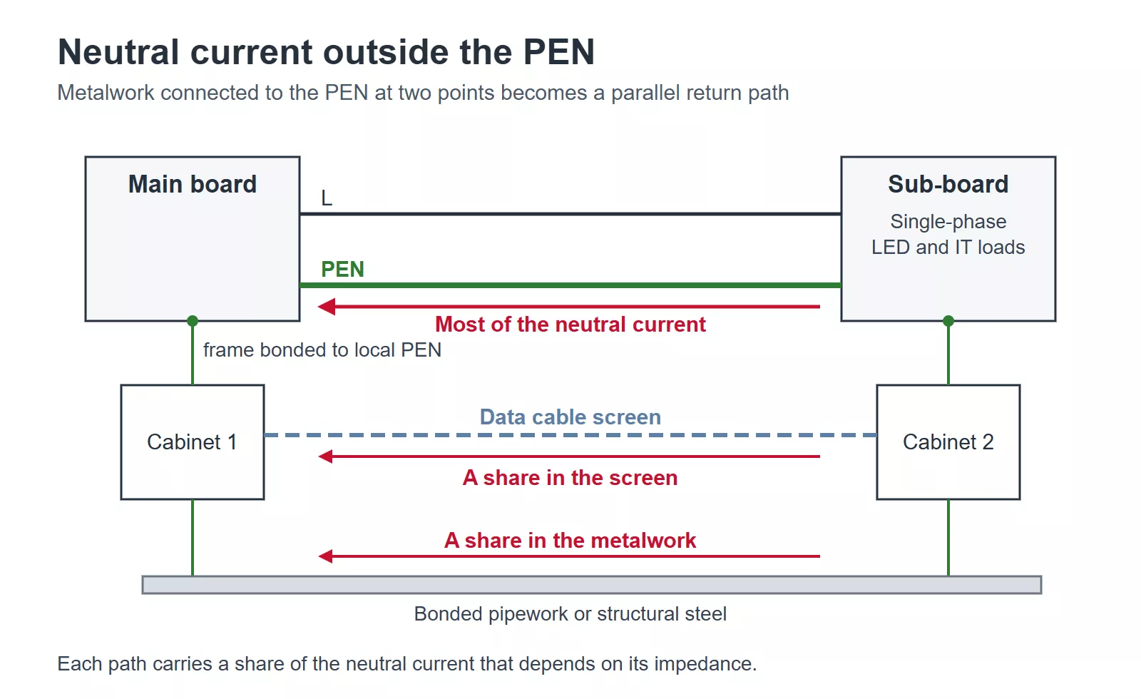
Figure 2 — In a TN-C installation, part of the neutral current returns through bonded pipework and a data cable screen that connect the PEN at two points.
The data cable screen in Figure 2 is a common case. Two cabinets on different boards each have their frame bonded to their local PEN, and a screened data cable runs between them. The screen joins the two PENs, so it carries a share of the neutral current. Modern loads make it worse. LED drivers and IT power supplies connected line to neutral draw triple-n harmonics, which add up in the neutral even when the phases are balanced, so the neutral current can be as large as a phase current. How much of it the screen takes depends on the impedance of each path, but on a long PEN run the share is enough to notice.
The results are hum on audio and video lines, data errors, heating at poor joints, and stray magnetic fields from cables whose currents no longer sum to zero. IEC 60364-4-44, the part that deals with electromagnetic disturbances, recommends TN-S over TN-C for buildings with a significant amount of IT equipment. Of the three drawbacks, this is the one most likely to cause trouble in a modern building, and the one a TN-C to TN-C-S conversion removes.
Converting TN-C to TN-C-S in an existing building
A TN-C installation becomes TN-C-S at the point where the PEN is split into a separate neutral and protective conductor. Done properly, everything downstream of the split behaves like TN-S: RCDs work, neutral current stays in the neutral, and SPDs can be connected in the usual way. It takes three things.
A split point with a PEN that qualifies. The split goes at the main board of the installation, where the incoming PEN is large enough to be a PEN in the first place. In an older apartment building, the conductor feeding an individual flat is often too small for that, so the split has to happen further up, at the building’s main board, which is work for the building owner and usually needs the network operator’s agreement. Many national rules also require the PEN to be connected to a local earth electrode at the split; check what yours asks for.
A split that only goes one way. The incoming PEN lands on the protective earth bar first. A link then connects the earth bar to a separate neutral bar, and from there on the neutral and the protective conductor never meet again. Connecting them a second time anywhere downstream recreates a PEN and brings the neutral current back into the metalwork.
New circuits with a real protective conductor. Moving a link at the board does not give an old circuit a protective conductor. Every circuit on the TN-C-S side needs its own PE run from the split: three-core cable for a single-phase circuit, and line conductors plus PE, with a neutral where the load needs one, for three-phase circuits. Old two-wire circuits stay what they were, either unearthed or still relying on a small PEN, until they are rewired.
One shortcut needs a direct warning. Earthing a new socket by bridging its earth terminal to the neutral, sometimes called classic zeroing, recreates a PEN at the socket with a final-circuit conductor that is far too small to be one. If that neutral breaks, or a plug or socket is wired with line and neutral swapped, the appliance case connects straight to line voltage.
Splitting the PEN inside the building does not remove it from the supply. The PEN upstream of the split, in the riser or the street cable, can still break, and a broken supply PEN lifts the voltage of the whole earth bar with it, which an RCD cannot detect. That is one reason many rules want the local earth electrode at the split: it holds the earth bar closer to true earth if the supply PEN fails.
How to connect an SPD in a TN-C system
Where the PEN is still combined, an SPD has only one place to go: from each line conductor to the PEN. That is the 3+0 connection, three protection modes and no fourth one. Because the PEN is both neutral and earth, each line-to-PEN mode protects line to neutral and line to earth at the same time, and there is no neutral-to-earth mode to add. The same applies at the board where the PEN is split: the neutral and earth bars are linked a few centimetres apart, so a surge cannot build a meaningful voltage between them.
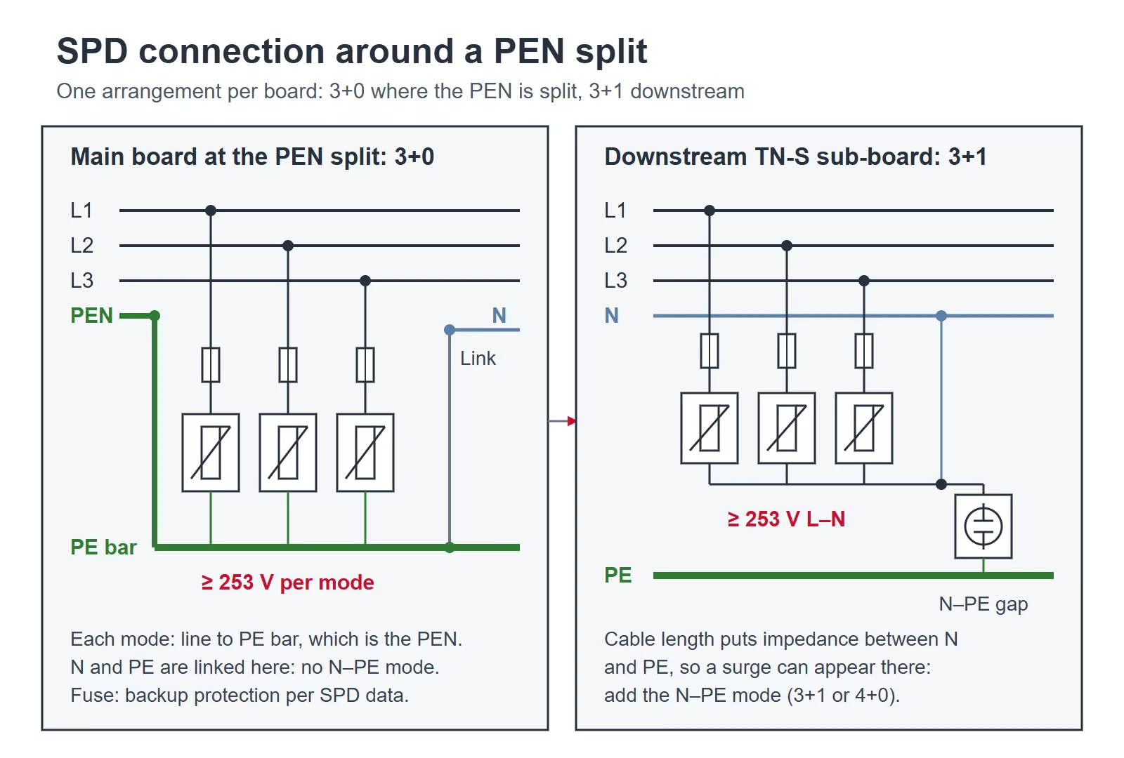
Figure 3 — SPD connection around a PEN split: 3+0 at the main board where the PEN is split, 3+1 at a downstream TN-S sub-board.
Further downstream it changes. A sub-board fed by a cable with separate neutral and protective conductors is on the TN-S side of the installation. The length of that cable puts impedance between its neutral and its earth, so a surge can now appear between them, and the sub-board SPD needs a neutral-to-earth mode as well: 3+1 or 4+0, chosen as in any TN-S board (4+0 vs 3+1 explained). Figure 3 shows the two positions as two boards, not one, because each board takes one SPD arrangement.
| Position | Conductors present | SPD connection | Minimum *Uc*, 230/400 V |
| TN-C board, or the main board at the PEN split | L1, L2, L3, PEN | 3+0, line to PEN | 253 V line to PEN |
| Downstream sub-board after the split | L1, L2, L3, N, PE | 3+1 or 4+0 | 253 V line modes |
The Uc minimum comes from IEC 60364-5-53: a mode between a line conductor and the PEN must be rated for at least 1.1 times the line-to-neutral voltage, 253 V on a 230/400 V supply. The standard 275 V class meets that, and a higher Uc is also acceptable at the main board, where the equipment is built for higher impulse voltages. A higher Uc raises the protection level Up, so the sub-boards feeding sensitive loads should carry their own SPD with a lower Up. Do not read Uc as a broken-PEN rating. A broken PEN is a temporary overvoltage, and how an SPD behaves under one is set by its TOV voltage, duration and safe failure mode on the datasheet, which applies to every SPD on that phase, upstream and downstream alike.
Whether the main board SPD is Type 1, Type 1+2 or Type 2 depends on the lightning exposure, not on the earthing system: Type 1 or Type 1+2 at the origin when the building has an external lightning protection system, when the supply comes in on an exposed overhead line, or when local rules call for it, and Type 2 otherwise. Keep the connecting leads from the line conductors and to the PEN bar as short as the board allows. Each metre of lead adds roughly 1 kV of inductive voltage during a fast surge, on top of the SPD’s own Up.
For a Type 2 position at a TN-C main board, Thor’s TRS4-C40 is available as a three-pole 3+0 unit, rated In 20 kA, Imax 40 kA, Uc 385 V AC and Up ≤1.8 kV, with plug-in modules that can be replaced without rewiring. For a downstream TN-S sub-board, the TRS2-C40 in 3P+N form gives the 3+1 connection at Uc 275 V on the line modes, 255 V neutral to earth, and Up ≤1.3 kV. The full range is on the Type 2 SPD page.
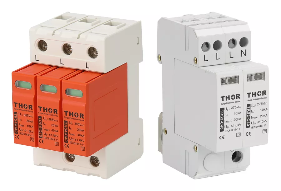
Figure 4 — Thor TRS4-C40 three-pole SPD for the main board (left) and TRS2-C40 3P+N SPD for a downstream sub-board (right).