A TN-S earthing system runs separate neutral (N) and protective earth (PE) conductors from the source transformer to every point in the installation — nothing combined, no shared PEN conductor. Three-phase TN-S uses five conductors: L1, L2, L3, N, and PE. The PE carries no current under normal operation, keeping the earth reference free of load currents and electrical noise.
The system is defined under IEC 60364-1 alongside four other earthing arrangements; the IET guidance on earthing covers installation requirements under BS 7671 for the same systems.
TN-S Wiring Diagram
A TN-S system uses five conductors in three-phase installations: L1, L2, L3, N, and PE. The neutral connects to earth at the transformer or generator — once, at the source. In a TN-S earthing system, N and PE travel as completely independent conductors from that separation point to every distribution board and load. Figure 1 illustrates this arrangement, showing the separation point at the source and the five-wire run to the main distribution board.
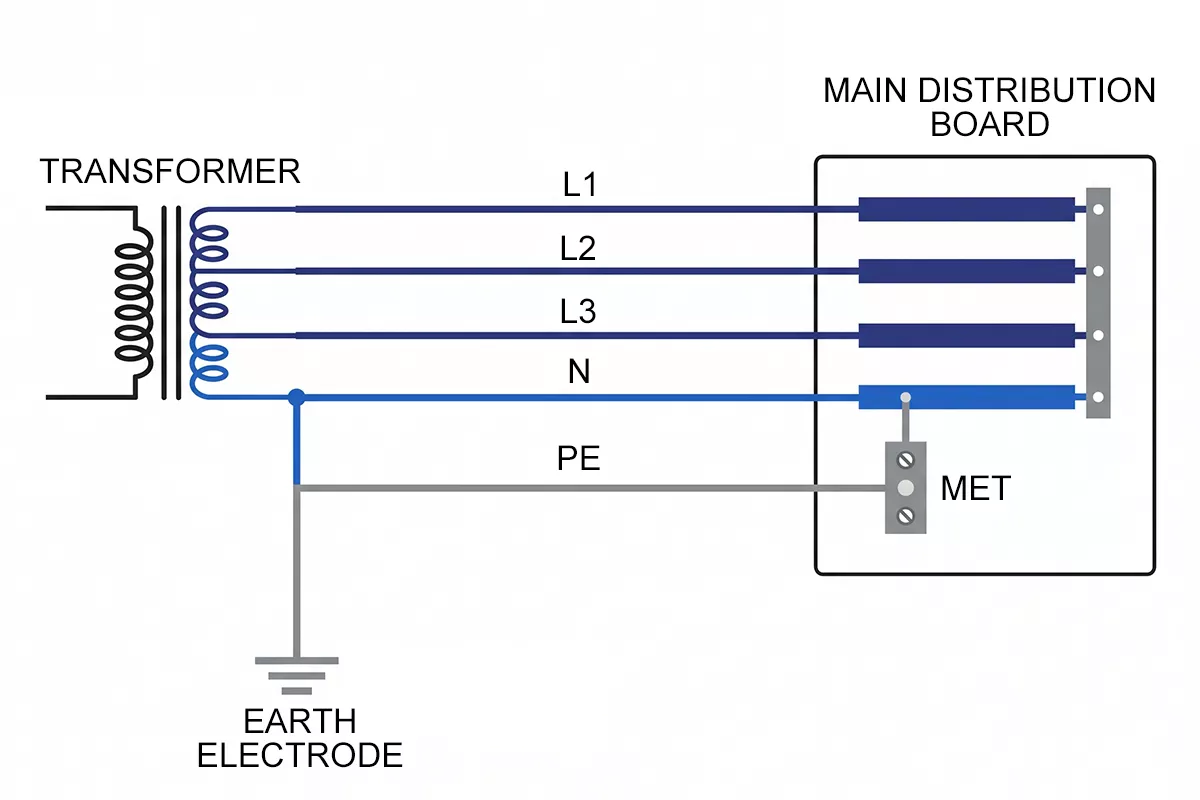
Figure 1 — TN-S earthing system wiring diagram: five-wire three-phase arrangement with separate N and PE conductors from source to distribution board
The PE conductor terminates at the main earthing terminal (MET) in the distribution board, where all equipment enclosures and exposed conductive parts connect to it. The neutral carries load return current. The PE carries nothing under normal operation — it only conducts during a fault, giving it a clean, low-impedance path to earth that is not contaminated by normal load currents or harmonic distortion on the N conductor.
In single-phase TN-S installations, the conductor count drops to three: L, N, and PE. The principle is identical — N and PE remain separate from source to load.
Advantages and Limitations of TN-S
TN-S earthing system has been the reference standard for high-quality electrical installations since the 1930s. The separate PE conductor is both its defining feature and the source of its one significant drawback.
The clearest advantage is electrical separation. Because N and PE never share a conductor, load return currents and harmonic distortion stay on the neutral and never appear on the protective earth. Equipment connected to the PE sees a genuinely clean earth reference — important for sensitive electronics, measurement systems, variable speed drives, and medical equipment where N-PE noise causes interference or measurement error.
Fault detection is also more reliable in a TN-S system. Any line-to-PE fault produces a short-circuit current large enough to trip the overcurrent protective device quickly. There is no ambiguity about the fault path, and no risk of the PE rising to a dangerous voltage due to a broken shared conductor — a failure mode specific to TN-C-S.
The limitation is cost. Running a dedicated PE conductor alongside N throughout the entire installation adds conductor material, conduit space, and termination work compared to TN-C-S, which combines N and PE into a single PEN conductor on the supply side. For large sites with long cable runs, the difference is measurable.
| TN-S | |
| Conductor count (3-phase) | 5 (L1, L2, L3, N, PE) |
| N and PE | Separate throughout |
| Earth noise on PE | None under normal operation |
| Fault detection | Reliable — clear short-circuit path |
| PEN failure risk | Not applicable |
| Typical applications | Industrial, hospitals, data centres, sensitive equipment |
| Relative installation cost | Higher than TN-C-S |
TN-S vs TN-C-S: Key Differences
TN-S and TN-C-S are the two most common earthing systems in industrial and commercial installations, and the distinction matters when specifying SPDs and designing fault protection.
In a TN-C-S system — also known as PME (Protective Multiple Earthing) — the supply runs a combined PEN conductor from the substation to the building entry point, where it splits into separate N and PE conductors for the internal installation. The TN-C-S earthing system article covers this arrangement in detail. TN-S keeps N and PE separate from the transformer all the way through — there is no PEN conductor at any point.
| TN-S | TN-C-S | |
| Supply conductors (3-phase) | 5 (L1, L2, L3, N, PE) | 4 (L1, L2, L3, PEN) |
| N/PE separation point | At the source | At building entry |
| PEN conductor present | No | Yes (supply side) |
| PEN open-circuit risk | Not applicable | Exists — PE can rise to line voltage |
| N-PE noise isolation | Complete | Partial |
| Max Ze (typical) | 0.8 Ω | 0.35 Ω |
| SPD connection | 3+1 | 3+1 |
| Typical use | Industrial, sensitive loads | Commercial buildings, PME areas |
Ze values are typical distributor limits per IEC 60364-1; actual values depend on network configuration.
Figure 2 illustrates the impedance difference between the two systems — TN-S’s longer separate PE conductor path results in a higher Ze, while TN-C-S benefits from the lower impedance of its metallic PEN supply route.
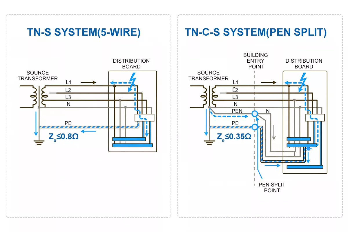
Figure 2 — TN-S vs TN-C-S earth fault loop impedance comparison: TN-S separate PE conductor gives higher Ze (≤0.8 Ω) than TN-C-S metallic PEN path (≤0.35 Ω)
The practical consequence of that difference is fault behaviour. If the PEN conductor in a TN-C-S supply breaks between the substation and the building, the PE inside the installation loses its earth reference and can rise toward line voltage — a potentially dangerous condition. TN-S earthing system has no PEN conductor, so that failure mode does not exist.
Figure 3 illustrates both systems side by side, showing where the conductors separate in each arrangement.
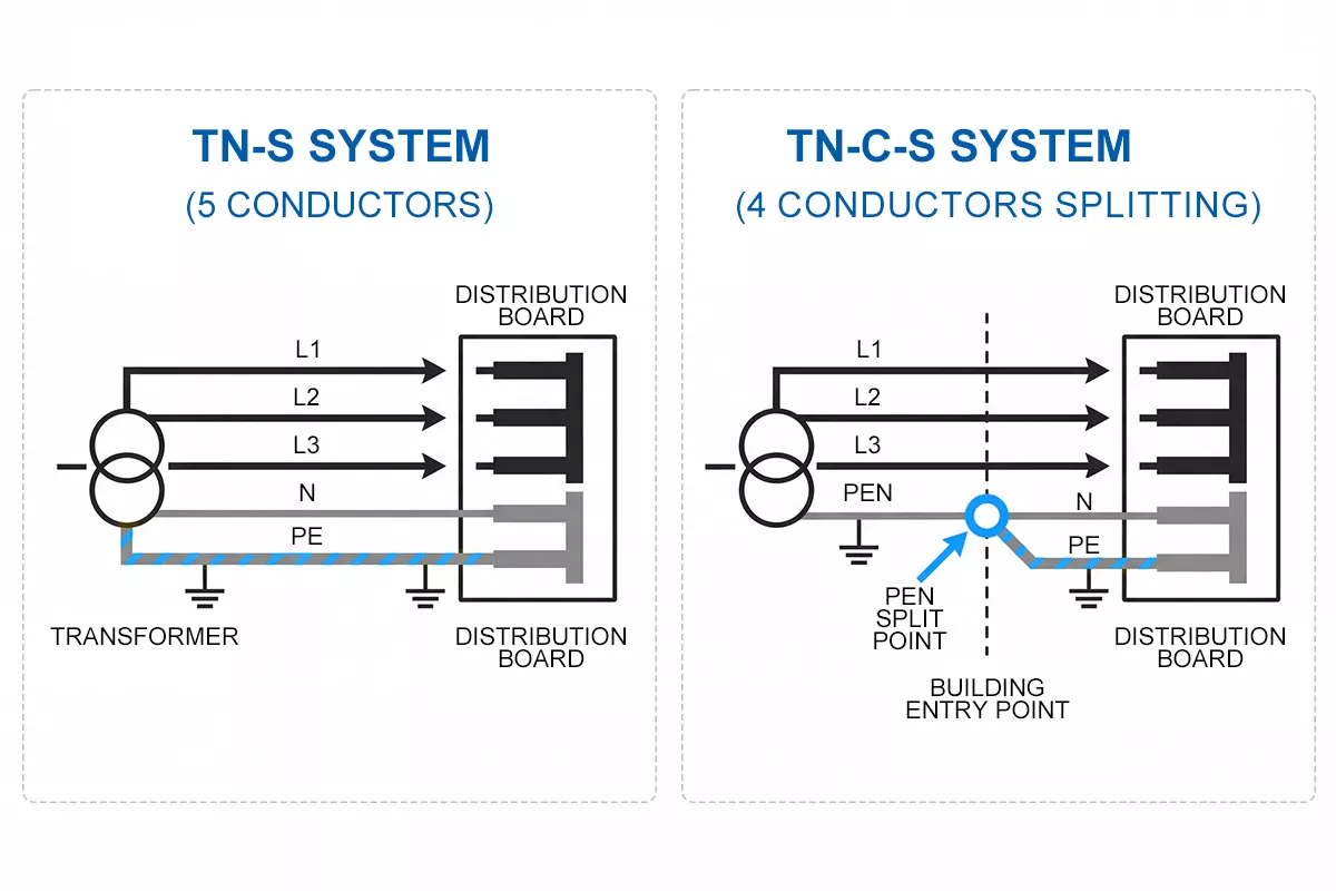
Figure 3 — TN-S vs TN-C-S wiring comparison: five-wire TN-S on the left, four-wire TN-C-S with PEN split at building entry on the right
TN-S vs TT vs IT: Quick Comparison
The three earthing systems appear in different installation contexts, and procurement engineers working across multiple sites or regions will encounter all of them. The table below covers the key distinctions.
| TN-S | TT | IT | |
| Source neutral | Earthed at source | Earthed at source | Isolated or high-impedance earthed |
| Consumer earth | Supplied via PE from source | Local earth electrode | Local earth electrode |
| Conductor count (3-phase) | 5 | 4 + local earth | 3 or 4 + local earth |
| First fault behaviour | Trips OCPD immediately | RCD required for reliable disconnection | No disconnection — insulation monitoring required |
| Continuity of supply | Interrupted on fault | Interrupted on fault | Maintained on first fault |
| Typical applications | Industrial, hospitals, data centres | Rural supplies, EV charging, areas without PME | Operating theatres, oil platforms, process plants |
| SPD connection | 3+1 | 3+1 or 1+1 | 3+0 or 1+0 |
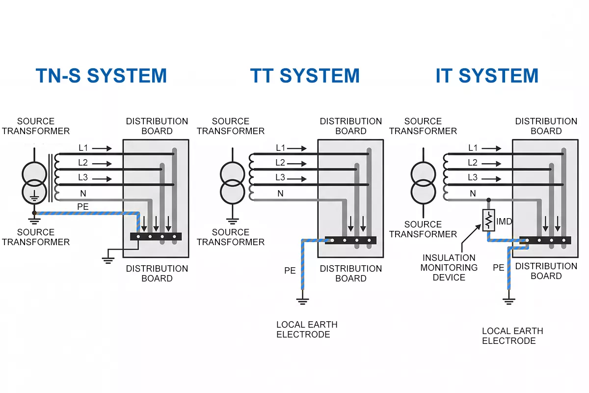
Figure 4 — TN-S, TT and IT earthing system comparison: conductor arrangement and earth connection method for each system type
IT systems are the outlier here. The isolated neutral means a single line-to-earth fault does not create a complete circuit, so the installation keeps running. A second fault on a different phase, however, produces a dangerous short-circuit condition — which is why IT systems require continuous insulation monitoring equipment to detect the first fault before a second one occurs.
For SPD selection, the earthing system determines the connection mode. TN-S and TT both use 3+1 in three-phase installations — L1, L2, L3 connected to PE through one set of MOVs, and N connected to PE through a separate MOV. IT systems use 3+0 or 1+0, connecting phase conductors directly to PE without involving the neutral, because introducing an N-PE MOV in an IT system would create an unwanted earth reference path that conflicts with the isolated neutral design. Getting the connection mode wrong negates the protection the SPD is there to deliver.
SPD Configuration for TN-S Systems
TN-S installations use 3+1 connection mode for three-phase systems: L1, L2, and L3 each connect to PE through one metal oxide varistor (MOV), and N connects to PE through a separate MOV. Single-phase TN-S uses 1+1: L to PE, and N to PE independently.
The reason the N-PE MOV matters in TN-S earthing system specifically comes down to what happens during a surge. Even though N and PE are separate conductors with no shared path under normal operation, a transient event can drive a voltage difference between them at the point of installation — particularly on long cable runs where the impedance of the N conductor is non-negligible. Without N-PE protection, that transient appears directly across equipment connected between neutral and earth, bypassing the L-PE MOVs entirely. The 3+1 configuration closes that gap.
As shown in Figure 5, the SPD installs at the main distribution board, as close to the incoming supply as the lead length allows. Total lead length — line conductor plus earth conductor combined — must stay below 0.5 metres. Each additional metre adds roughly 1 µH of parasitic inductance, which at a surge rise rate of 10 kA/µs translates to 10 kV of additional voltage on top of the SPD’s rated Up. A well-specified SPD with poor installation geometry will underperform a modest SPD installed correctly.
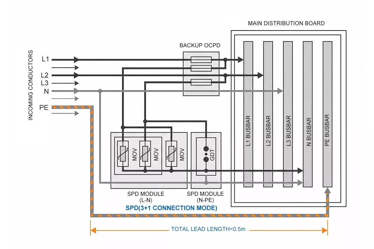
Figure 5 — SPD 3+1 connection diagram for TN-S three-phase system: L1, L2, L3 to PE through MOVs, N to PE through separate MOV, installed at main distribution board
TN-S earthing systems use 3+1 rather than 4+0 because the neutral conductor is present and carries return current. A 4+0 configuration connects L1, L2, L3, and N all to PE through MOVs — it is designed for systems where no neutral exists, such as IT installations or certain delta-connected supplies. In a TN-S system with a dedicated neutral, omitting N-PE protection leaves a gap that a transient can exploit. 3+1 closes it.
For a full explanation of both connection modes, the 4+0 and 3+1 configuration article covers the wiring logic and selection criteria in detail.
For most TN-S industrial and commercial installations, Thor’s TRS4-C40 covers the standard requirement: In 20 kA, Imax 40 kA, Uc 275V AC, Up ≤1.5 kV, certified to IEC 61643-11. The 3P+N configuration maps directly to the 3+1 connection mode required for TN-S system. Where the installation sits close to a lightning protection system or in a high keraunic zone, step up to the TRS5-B+C Type 1+2, which adds Iimp 12.5 kA on the same footprint.
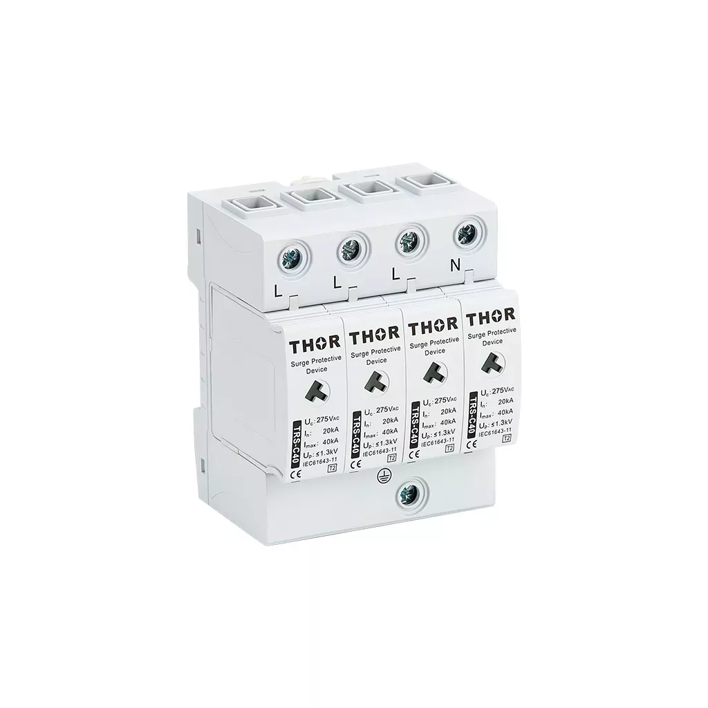
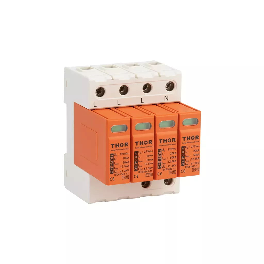
Figure 6 — Thor TRS4-C40 Type 2 AC SPD and TRS5-B+C Type 1+2 AC SPD, both in 3P+N configuration for TN-S three-phase installations
FAQ
What is a TN-S earthing system?
A TN-S earthing system is a grounding arrangement defined in IEC 60364-1 where the supply neutral (N) and protective earth (PE) run as completely separate conductors from the source transformer to every point in the installation. Three-phase TN-S supplies use five conductors: L1, L2, L3, N, and PE. The PE carries no current under normal operation — it only conducts during a fault, keeping the earth reference free of load current and electrical noise.
What is the difference between TN-S and TN-C-S?
In a TN-S system, N and PE are separate conductors from the source all the way through the installation. In a TN-C-S system, the supply uses a combined PEN conductor from the substation to the building entry point, where it splits into separate N and PE for the internal wiring. The practical difference is fault safety: if the PEN conductor in a TN-C-S supply breaks, the PE inside the installation can rise toward line voltage. TN-S has no PEN conductor, so that failure mode does not exist. For a full breakdown of both systems, the TN-C-S earthing system article covers the wiring, advantages, and SPD configuration in detail.
What SPD connection mode does a TN-S system require?
TN-S three-phase installations require 3+1 connection mode: L1, L2, and L3 each connect to PE through a MOV, and N connects to PE through a separate MOV. The N-PE MOV is not optional — a surge can drive a voltage difference between N and PE even in a TN-S system, and without that protection the transient bypasses the L-PE MOVs and reaches the load directly. Single-phase TN-S uses 1+1: L to PE and N to PE independently.
How does a TT earthing system differ from TN-S?
In a TN-S earthing system, the protective earth conductor runs back to the source transformer — the consumer relies on the supplier’s earth. In a TT system, the source neutral is earthed at the substation, but the consumer must install their own local earth electrode; no PE is provided by the distributor. TT systems require RCDs for reliable fault disconnection because the fault loop impedance through a local earth electrode is typically too high to trip a standard overcurrent device. TN-S fault currents are higher and trip OCPDs without needing an RCD.
What is the earth fault loop impedance of a TN-S system?
The maximum earth fault loop impedance (Ze) for a TN-S supply is typically 0.8 Ω at the origin of the installation, compared to 0.35 Ω for TN-C-S. The higher impedance reflects the longer, separate PE conductor path back to the source. Higher Ze means lower prospective fault current, which must be factored into overcurrent protective device selection to confirm that fault currents are still sufficient to trip within the required disconnection time per IEC 60364-4-41.
Thor Electric AC Surge Protection Devices
Thor Electric manufactures Type 1, Type 2, and Type 1+2 AC SPDs certified to IEC 61643-11, covering single-phase and three-phase installations including TN-S, TN-C-S, and TT systems. The TRS4 series is available in 3P+N configuration for direct 3+1 deployment in TN-S distribution boards, with samples and custom Uc variants available on request. For project-specific SPD specifications or bulk procurement inquiries, contact the Thor Electric team at https://spds.global/contact-us/.