An SPD gives no warning when it stops working.
A circuit breaker trips and holds — you see it, you reset it, you know something happened. A surge protection device absorbs the hit silently, degrades internally, and stays in the panel looking identical whether it has full protection capacity or none at all. In a facility without a maintenance plan, the SPD that took a direct lightning-induced surge six months ago may already be a hollow shell — still wired in, still green on the indicator, but offering zero clamping protection against the next event.
The reason lies in the material. The active element inside a voltage-limiting SPD is a metal oxide varistor (MOV) — a sintered body of zinc oxide (ZnO) granules. Every time the MOV clamps a transient, the energy dissipated at the grain boundaries causes microscopic structural damage. The grain boundary resistance shifts, the clamping voltage (Up) drifts upward, and the device’s remaining discharge capacity drops. The degradation mechanism is well-documented; see, for example, the durability model for MOV surge degradation in Kim et al. (2022) .
The grain boundary resistance shifts, the clamping voltage (Up) drifts upward, and the device’s remaining discharge capacity drops. The process is cumulative and irreversible. It does not reset between events.
Effective surge protection device maintenance rests on three layers: scheduled inspection aligned with IEC 62305, event-triggered checks after surges or system changes, and continuous remote monitoring via dry contacts. The sections below cover each layer, how to read the fault indicator correctly, and when to replace versus when to investigate the root cause first.
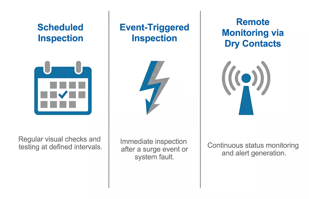
Figure 1: Three-layer SPD maintenance framework — scheduled inspection / event-triggered checks / remote monitoring.
Why SPDs Need a Maintenance Plan
Surge protective devices sit in standby for months or years between events. That dormancy creates a false sense of security: if nothing has visibly changed, the assumption is that nothing has failed. In practice, SPD degradation follows a different pattern.
Each surge event — whether from a direct lightning strike, a nearby indirect strike, or a switching transient on the distribution network — passes a pulse of energy through the MOV. The MOV absorbs it, but the ZnO grain boundaries accumulate damage with every cycle. As the material degrades, two things happen: Up rises gradually above the rated value, and the thermal disconnector inside the device gets closer to its trip threshold. At some point, the disconnector opens, the indicator window turns red, and the device is offline.
The problem with open-circuit failure is that it can go unnoticed for months in any installation without a monitoring routine. The panel looks normal. The wiring is intact. Only the SPD has quietly stopped protecting.
Short-circuit failure is less common but more disruptive. When an SPD fails short, the upstream overcurrent protective device — fuse or circuit breaker — trips to clear the fault. That at least creates a visible event. But in a panel without remote monitoring, a tripped SCPD upstream of the SPD can go undetected in an unmanned substation or remote enclosure until the next site visit.
Both failure modes are avoidable with a structured maintenance programme.
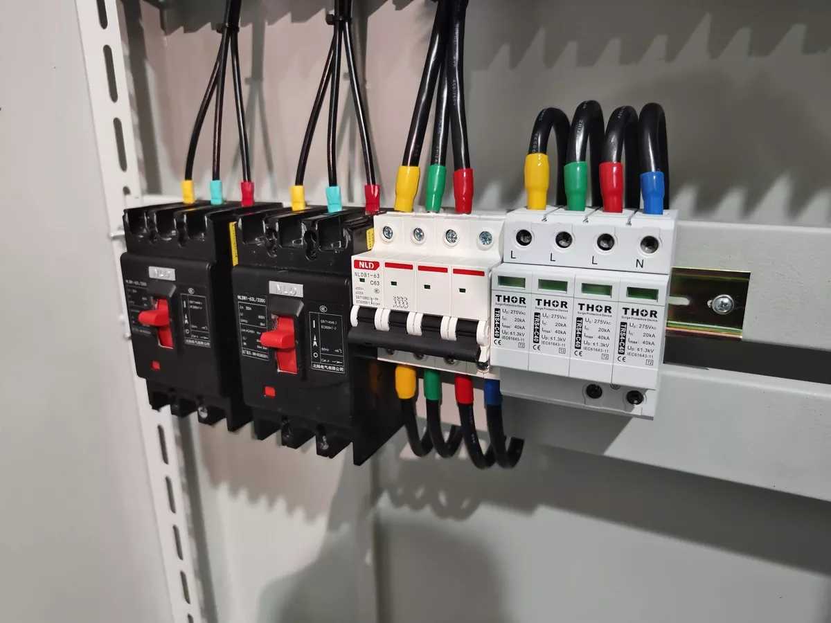
Figure 2: Thor SPDs installed in industrial distribution panel, indicator windows visible.
Inspection Schedule: What IEC 62305 Requires
IEC 62305 does not assign a single fixed interval to every installation. The required inspection frequency depends on the Lightning Protection Level (LPL) assigned to the facility and the site risk profile.
For most industrial installations, the baseline is:
| Inspection Type | LPL I | LPL II / III / IV | High-Risk / Mission-Critical |
| Visual inspection | 12 months | 24 months | 3–6 months |
| Full inspection | 12 months | 24 months | 3–6 months |
| Post-event inspection | After any confirmed surge, lightning strike, switching fault, or system modification | ||
A full inspection covers more than a glance at the indicator window. Check terminal torque, upstream SCPD condition, enclosure integrity, any signs of thermal stress on the housing, and the surge event log if remote monitoring is active.
Event-triggered inspection sits outside the scheduled cycle and cannot be skipped. An SPD that absorbed a major lightning-induced surge last Tuesday may still show a green indicator today — the thermal disconnector has not yet tripped — but the MOV’s remaining capacity may be critically low. Post-storm checks after confirmed lightning activity in the area are standard practice in well-run industrial facilities, not optional.
IEC 61643, the product standard that governs how SPDs are designed and tested, does not prescribe maintenance intervals. It drives device selection and verification — the Imax, In, and Uc ratings that determine whether the SPD is correctly specified for the site. Maintenance intervals come from IEC 62305 and the manufacturer’s recommendations, cross-referenced against the site’s actual surge exposure history.
For facilities where the LPL classification is unclear, annual visual inspection plus post-event checks is the safe default.
Reading the Fault Indicator
The indicator window on a modular SPD communicates one thing: whether the internal thermal disconnector is open or closed. Reading it correctly requires knowing what each state means for your specific device — because “no light” does not always mean the same thing across manufacturers and models.
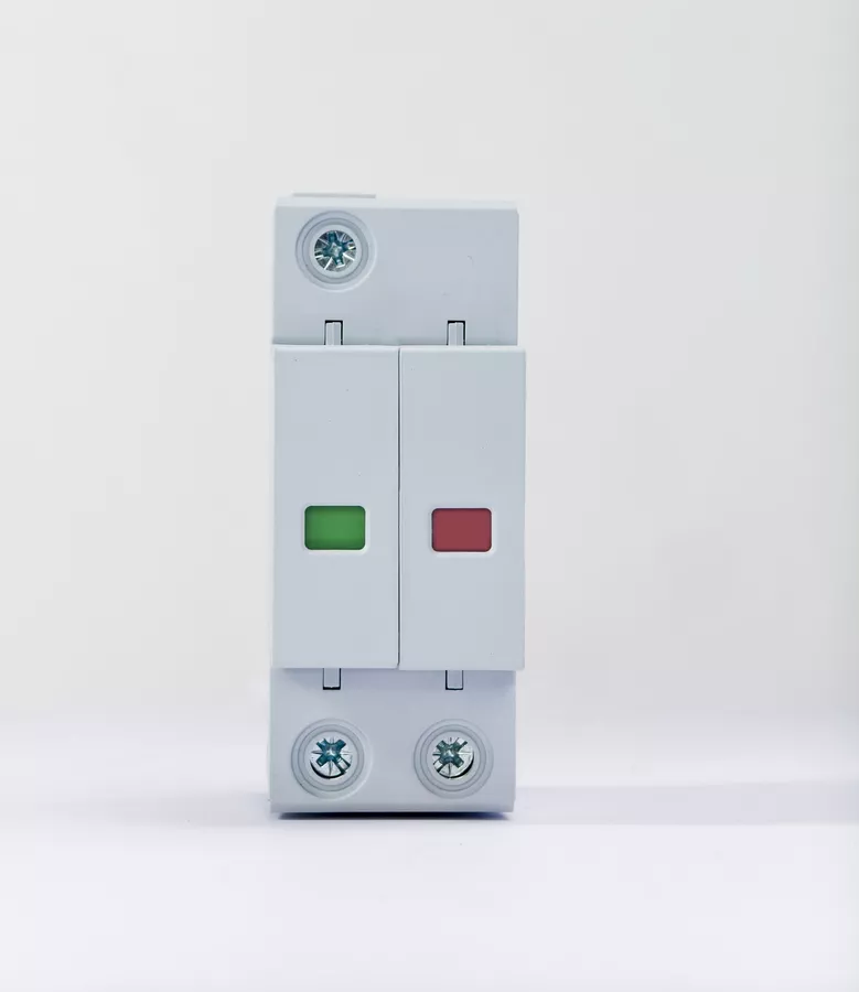
Figure 3: SPD indicator window showing green (normal) and red (fault) states side by side.
Green indicator / window clear:
The thermal disconnector is closed. The MOV is in circuit and the device is actively protecting. This is normal operating state.
Red indicator / flag tripped:
The thermal disconnector has opened and disconnected the MOV from the circuit. The device is no longer protecting. Replace the module.
A red indicator does not automatically mean the SPD was overwhelmed by a surge beyond its rating. Three causes are common in field installations:
- Normal end-of-life: The MOV accumulated sufficient degradation over multiple surge events that the disconnector tripped at its threshold. Expected behaviour — replace and log.
- Wrong Uc selection: If the selected Uc is lower than the actual sustained line voltage at the installation point — including long-term interference voltages on the network — the MOV operates in continuous partial conduction, overheats, and the disconnector trips prematurely. This is a specification error, not a surge event. Replacing the module without correcting the Uc selection will result in repeated early failures.
- Mechanical disconnection: Vibration during transport or installation, or thermal cycling stress over time, can crack the disconnector contacts. The indicator trips without any electrical cause.
No indicator / light off:
This state is model-dependent. On some SPDs, a dark indicator means the device has lost power or the indicator lamp itself has failed — neither of which confirms the MOV is still functional. On others, the indicator is only lit during a fault state, so dark means normal. Check the datasheet for your specific model before drawing conclusions.
Thor TRS series SPDs use a mechanical visual indicator window — the flag is physically driven by the thermal disconnector, not powered by an LED circuit. A red window means the disconnector has opened, with no ambiguity from lamp burnout.
Remote Monitoring via Dry Contacts
A visual indicator tells you the SPD has failed — but only if someone is standing in front of the panel to see it. In large industrial facilities, solar farms, telecom towers, and unmanned substations, that condition is rarely met between scheduled maintenance visits. A module that tripped two weeks ago may not be discovered until the next site inspection. In the meantime, the installation is unprotected.
Dry-contact remote monitoring solves this directly.
The dry contact inside an SPD is a volt-free switching element connected to the device’s internal status circuit. When the SPD is operating normally, the contact holds one state — typically closed. When the thermal disconnector opens and the module goes offline, the contact switches state. That signal is routed to a building management system (BMS), SCADA panel, or standalone alarm unit, triggering an alert without anyone opening the enclosure.
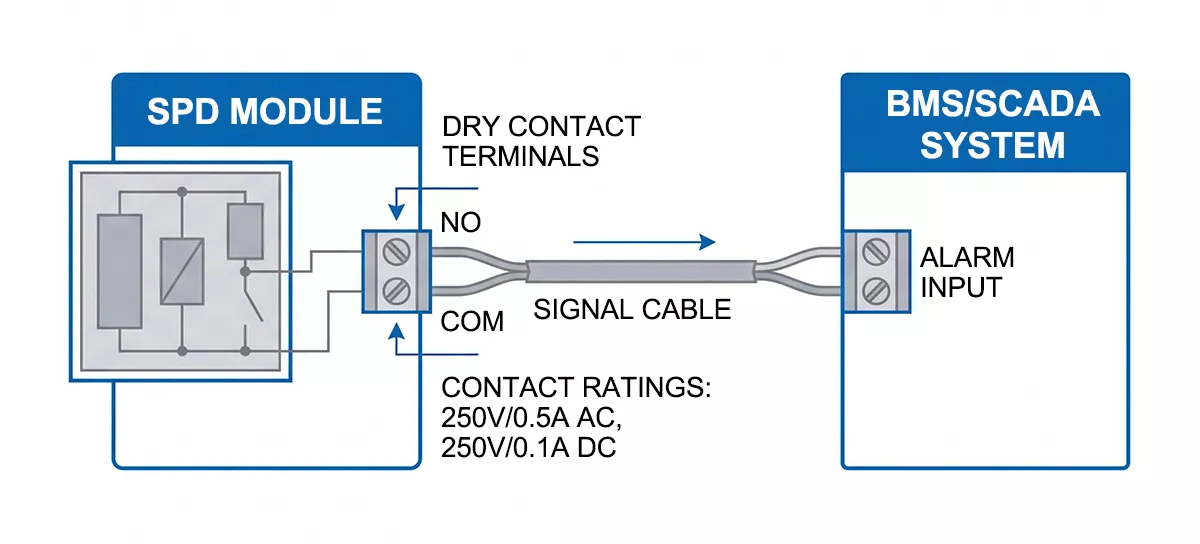
Figure 4: Dry contact wiring schematic — SPD remote signal contact wired to BMS/alarm panel.
The contact itself carries no surge current and handles no power switching. Its only function is status signalling. Thor TRS series remote signal contacts are rated at 250V/0.5A AC and 250V/0.1A DC — sufficient for integration into standard industrial alarm and monitoring circuits.
Specifying remote monitoring makes the most operational sense in:
- Large industrial sites with multiple distribution boards and SPDs across a wide area
- Solar PV installations where DC-side SPDs at combiner boxes may be in remote field enclosures
- Telecom towers and unmanned substations where site visits are infrequent
- Mission-critical facilities — data centres, hospitals, water treatment plants — where any gap in surge protection carries significant downside risk
Remote monitoring does not replace scheduled inspection. Terminal condition, enclosure integrity, and upstream SCPD status cannot be checked from a BMS dashboard. What dry contacts do is eliminate the worst-case scenario: a failed SPD that goes undetected for months because no one happened to look at it.
SPD Maintenance Checklist
The table below covers the minimum checks for an industrial SPD installation. Use it during scheduled inspections and immediately after any surge event, lightning activity, or upstream fault.
| Check Item | Frequency | Pass Criteria | Action if Failed |
| Visual fault indicator | Every visit | Green / window clear | Replace module immediately |
| Enclosure condition | Every visit | No cracks, no scorch marks, no moisture ingress | Identify cause before re-energising |
| Terminal torque | Annual / post-event | Connections secure, no discolouration at terminals | Re-torque to spec; replace if discoloured |
| Upstream SCPD status | Every visit | Fuse intact / breaker in ON position | Replace fuse or reset breaker; investigate cause |
| Thermal signs on housing | Every visit | No melting, no burn odour, no soot | De-energise; full inspection before restart |
| Earthing / PE conductor | Annual | PE connection secure; earthing resistance within site spec | Recheck earthing system — SPD protection is only as good as the earth path |
| Surge event log | Post-event | No unrecorded events since last inspection | Update log; schedule post-event inspection if surge confirmed |
| Replacement history | Annual | Module age and replacement dates documented | Replace modules with no documented history if site has active surge exposure |
| Remote signal contact | Annual | Contact state matches indicator status | Check wiring continuity; replace module if contact and indicator disagree |
Download the full checklist as a PDF .
When to Replace — and When to Investigate First
A red indicator means the module is offline and needs replacing. What the indicator does not tell you is why it tripped — and skipping that question is how facilities end up cycling through replacement modules every few months without fixing the underlying problem.
Replace immediately when:
- The fault indicator is red or the window flag has tripped
- The indicator is dark on a model where normal operation shows a lit state
- Visible burn marks, scorch, or melted plastic on the housing or surrounding enclosure
- The upstream SCPD has tripped and no other cause is identified
In all these cases, the module goes out and a replacement goes in before the installation is re-energised. With a pluggable modular SPD, that replacement takes minutes. The wiring base stays in place — terminals stay torqued, connections stay intact. Pull the spent cartridge, insert the replacement, confirm the indicator is clear. No rewiring, no panel downtime beyond the swap itself.
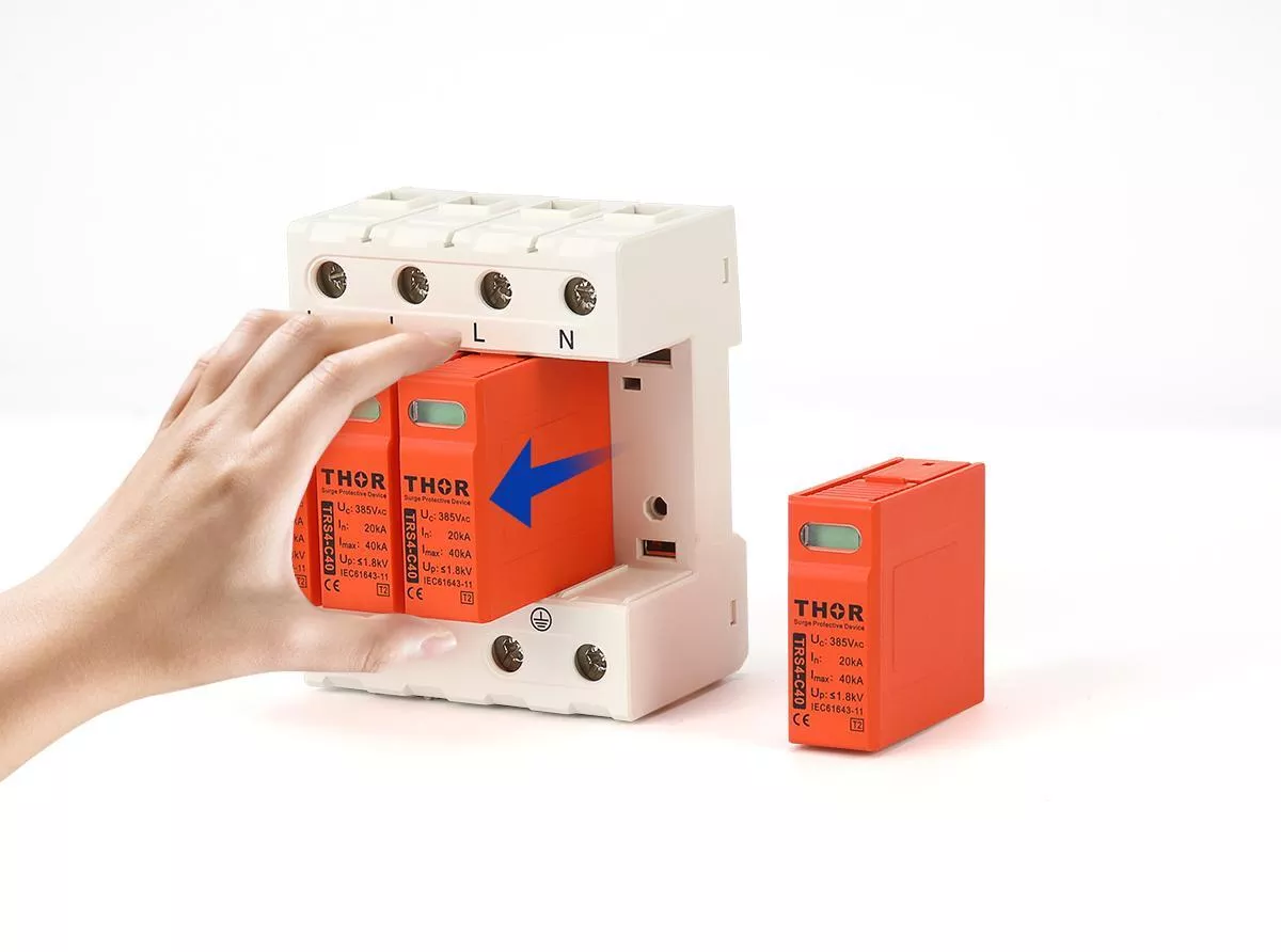
Figure 5: Pluggable SPD module being replaced — cartridge removal from wiring base with base terminals intact.
Non-modular SPDs require disconnecting the entire unit, removing the wiring, installing a replacement device, and re-terminating. In a live distribution board, that means a planned outage. The operational difference is significant on any site where uptime matters.
Investigate before replacing when:
The module is red, but this is the second or third replacement in an unusually short period. Repeated early failures point to a root cause that a new module will not fix.
Work through this sequence:
- Check Uc against actual line voltage. Measure the sustained voltage at the SPD terminals under normal load conditions, including peak interference periods if the site runs heavy inductive loads. If the actual voltage regularly approaches or exceeds the rated Uc, the MOV is operating in continuous partial conduction. Specify a higher Uc for the replacement — Thor TRS series Uc is available in 275V, 320V, and 385V AC configurations.
- Check upstream SCPD coordination. An undersized fuse or breaker upstream of the SPD can cause nuisance disconnections that look like SPD failure. Verify the SCPD rating matches the SPD manufacturer’s recommendation.
- Check the installation environment. High ambient temperature, poor ventilation, or proximity to heat sources accelerates MOV degradation. If the enclosure runs hot, address the thermal environment before installing the replacement.
- Check the surge exposure history. A site that takes multiple direct lightning-induced surges per year will consume SPD service life faster than the rated Imax figure suggests under single-event assumptions. Consider upgrading to a higher Imax rating or adding a Type 1 vs Type 2 vs Type 3 SPD upstream of the existing Type 2 installation.
The goal is not to preserve modules — they are consumables. Confirm the replacement will last a reasonable service life before the next inspection cycle.
FAQ
How often should surge protection devices be inspected in an industrial facility?
IEC 62305 sets the baseline: annual full inspection for LPL I installations, and every 24 months for LPL II, III, and IV. High-risk or mission-critical sites — data centres, hospitals, facilities with frequent lightning exposure — commonly operate on a 3–6 month schedule as a matter of maintenance policy. These intervals apply to scheduled inspection. Post-event checks after confirmed lightning activity, major switching faults, or upstream breaker trips are additional and cannot be deferred to the next scheduled visit.
What does a red indicator on an SPD mean?
The thermal disconnector inside the device has opened, taking the MOV out of circuit. The installation at that point has no surge protection on the affected mode — replace the module before re-energising. A red indicator does not necessarily mean the SPD was destroyed by a surge. Wrong Uc selection, sustained overvoltage, or mechanical stress during installation can all trigger the disconnector without a surge event occurring.
Can I replace just the module without rewiring the base?
On pluggable modular SPDs, yes. The wiring base remains in place and the cartridge pulls out and inserts without disturbing any terminal connections. On fixed non-modular devices, the entire unit must be removed and rewired. If your current installation uses non-modular SPDs and module-level replacement matters for your maintenance workflow, factor that into the next specification cycle.
What is the difference between visual inspection and remote monitoring for surge protection device maintenance?
Visual inspection confirms the physical condition of the device, terminals, enclosure, and upstream protection — things that cannot be assessed remotely. Remote monitoring via dry contacts signals fault state changes in real time, catching a tripped module between scheduled visits. The two are complementary: remote monitoring reduces the risk of an undetected failure, and visual inspection catches degradation that a contact state change alone will not reveal.
Does an SPD need replacing after every lightning strike?
Not automatically. Check the fault indicator first. If it is still clear, the device may have absorbed the event within its rated discharge capacity and remains operational. If the indicator has tripped to red, replace the module. The indicator reflects cumulative MOV degradation, not individual event count — a single high-energy strike can trip it; a series of low-energy events may not. On sites with active lightning exposure, a post-storm visual check is standard practice regardless of indicator state, and logging each event helps track cumulative surge history. For more on how degradation accumulates, see SPD aging and replacement.
Thor Electric Surge Protection Devices
Thor Electric manufactures a full range of AC and DC surge protection devices certified to IEC, TUV, CE, RoHS, CB and ISO standards. The TRS series uses a pluggable modular design with a mechanical visual indicator window and an optional remote signal contact rated at 250V/0.5A AC and 250V/0.1A DC, for direct integration into BMS and SCADA systems. Replacement modules, technical datasheets, and OEM configurations are available. For project specifications, sample requests, or a downloadable copy of the SPD maintenance checklist, contact Thor Electric at spds.global/contact-us/.