
For most three-phase 230/400V installations, a Type 2 SPD with Uc 275V AC wired in 3+1 mode covers standard distribution board protection. Where a building has an external lightning protection system or the service entrance is directly exposed to lightning, add a Type 1 or Type 1+2 at the main panel. Earthing system type — not panel size or load current — determines pole count and protection mode.
What Is a 3-Phase Surge Protection Device?
A 3-phase surge protection device is an IEC 61643-11-rated component installed in three-phase power distribution panels to clamp transient overvoltages and divert surge current away from downstream equipment. In a standard 230/400V system, surges can enter along three distinct paths: line-to-line (L-L, 400V), line-to-neutral (L-N, 230V), and line or neutral-to-protective earth (L/N-PE). A properly configured 3-phase SPD covers all three simultaneously. Single-phase devices protect one conductor pair; three-phase systems require protection across all live conductors and the neutral — which is why pole count and wiring mode matter as much as current rating.
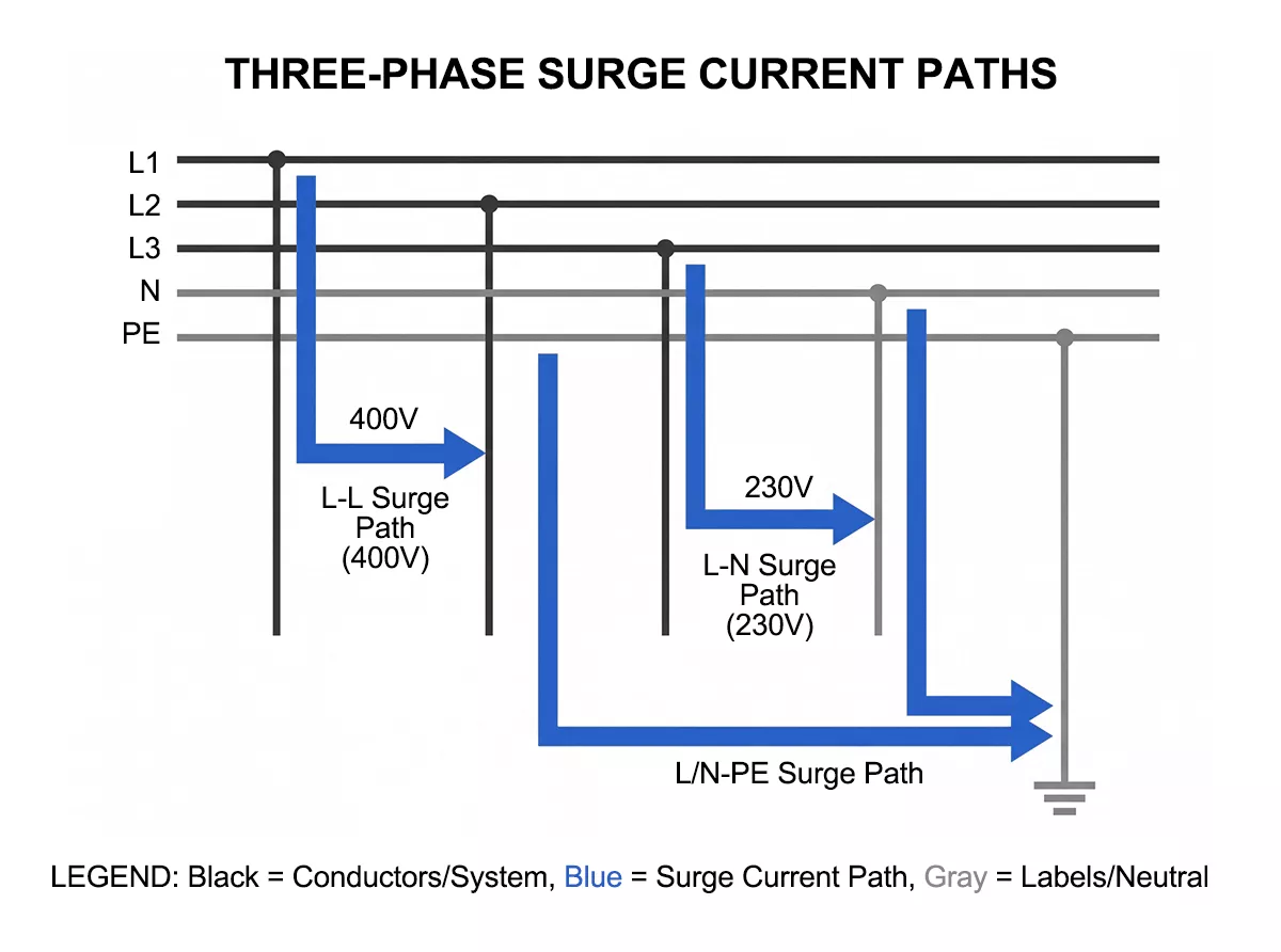
Figure 1. Surge current paths in a three-phase 230/400V system: L-L (400V), L-N (230V), and L/N-PE
Why Three-Phase Systems Need Surge Protection
Three-phase power runs the majority of industrial and commercial electrical loads — motors, variable frequency drives (VFDs), compressors, control panels. The surge environment in these installations differs from residential single-phase systems in two important ways.
First, surges have more entry paths. A lightning-induced transient on the grid hits all three phases, but switching events — motor start/stop, capacitor bank switching, load shedding — can create an imbalance that stresses only one or two phases. An SPD covering only L-PE on a single phase leaves the other two exposed.
Second, a transient affecting one or more conductors can disturb voltage conditions seen by three-phase loads. A correctly selected 3-phase SPD limits transient voltage across the protected conductors and reduces the stress passed to downstream three-phase equipment.
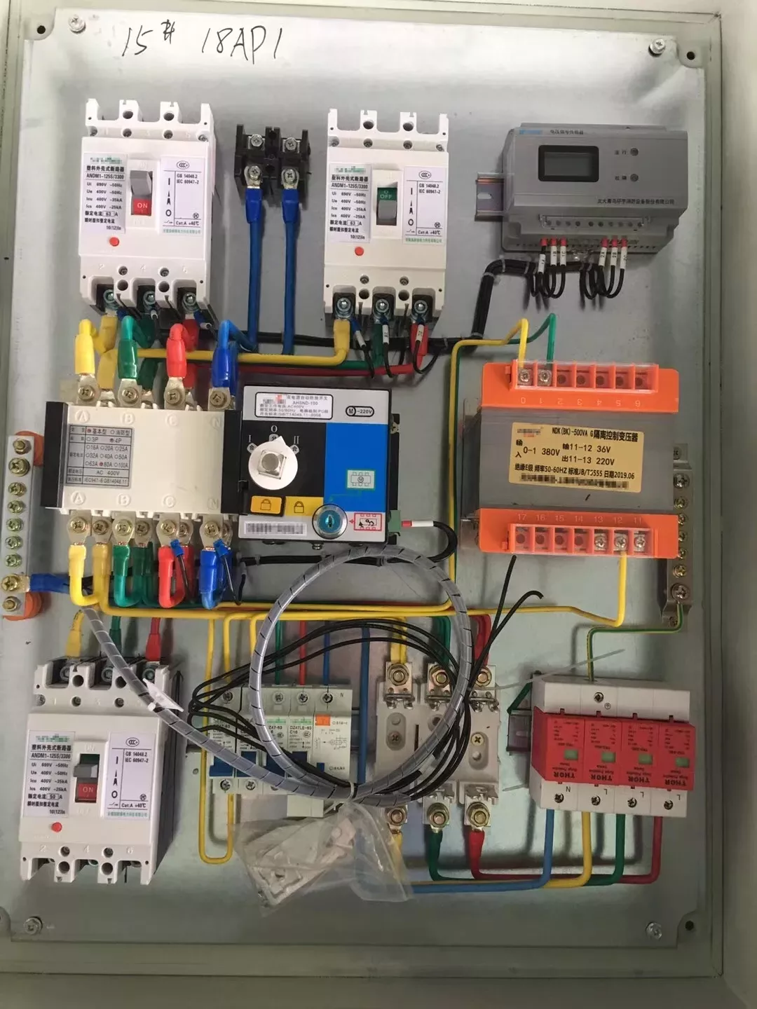
Figure 2. Three-phase industrial distribution panel with DIN-rail mounted SPD — typical installation environment for a 3-phase surge protection device
Internal surge sources — capacitor switching, motor starting, load shedding — account for a significant share of SPD activations in factory environments. Capacitor switching alone can generate surges with rise times under 1µs and peak voltages of 2–3× the nominal line voltage. These events repeat daily, degrading unprotected equipment gradually rather than catastrophically, which makes them harder to trace back to surge damage.
How to choose a 3-phase surge protection device
Choose a 3-phase surge protection device in four steps: identify the earthing system, decide whether Type 1 lightning-current protection is required, select the 3P or 3P+N connection mode, and verify Uc, In, Imax and Up against the installation. Load current does not size an SPD because the device is connected in parallel rather than in series with the load.
Installation position determines SPD type — not load size, not panel amperage. IEC 61643-11 defines three types based on the test waveform each device must survive.
| Type | Test waveform | Install position | When required |
| Type 1 | 10/350µs (Iimp) | Main panel / service entrance | LPS present or direct lightning exposure |
| Type 2 | 8/20µs (In / Imax) | Distribution board / sub-panel | Standard industrial and commercial |
| Type 1+2 | Both | Main panel | Space-limited; combined protection in one device |
Type 1 absorbs the high-energy partial lightning current that flows back into the installation when a building has an external lightning protection system (LPS). The 10/350µs waveform carries far more energy than the 8/20µs waveform used to test Type 2 devices — at the same peak current, the energy content is orders of magnitude higher. Without a Type 1 at the service entrance, that energy reaches the distribution board and overwhelms any Type 2 installed downstream. Thor Electric’s TRS-A series covers Type 1 protection, with Iimp ratings from 15kA to 50kA per pole.
Type 2 is the standard choice for distribution boards and sub-panels in industrial and commercial buildings. It clamps induced lightning surges and the switching transients generated internally by the installation. The TRS-B, TRS-C, and TRS-D series cover this range, with Imax from 10kA (TRS-D10) up to 100kA (TRS-B100).
Type 1+2 combines both functions in a single plug-in module — useful when the main panel has limited DIN rail space or when a separate Type 1 enclosure is impractical. The TRS5 series (Iimp 12.5kA, Imax 50kA) and the TUV-certified TRS30B+C (Imax 60kA) cover this category.
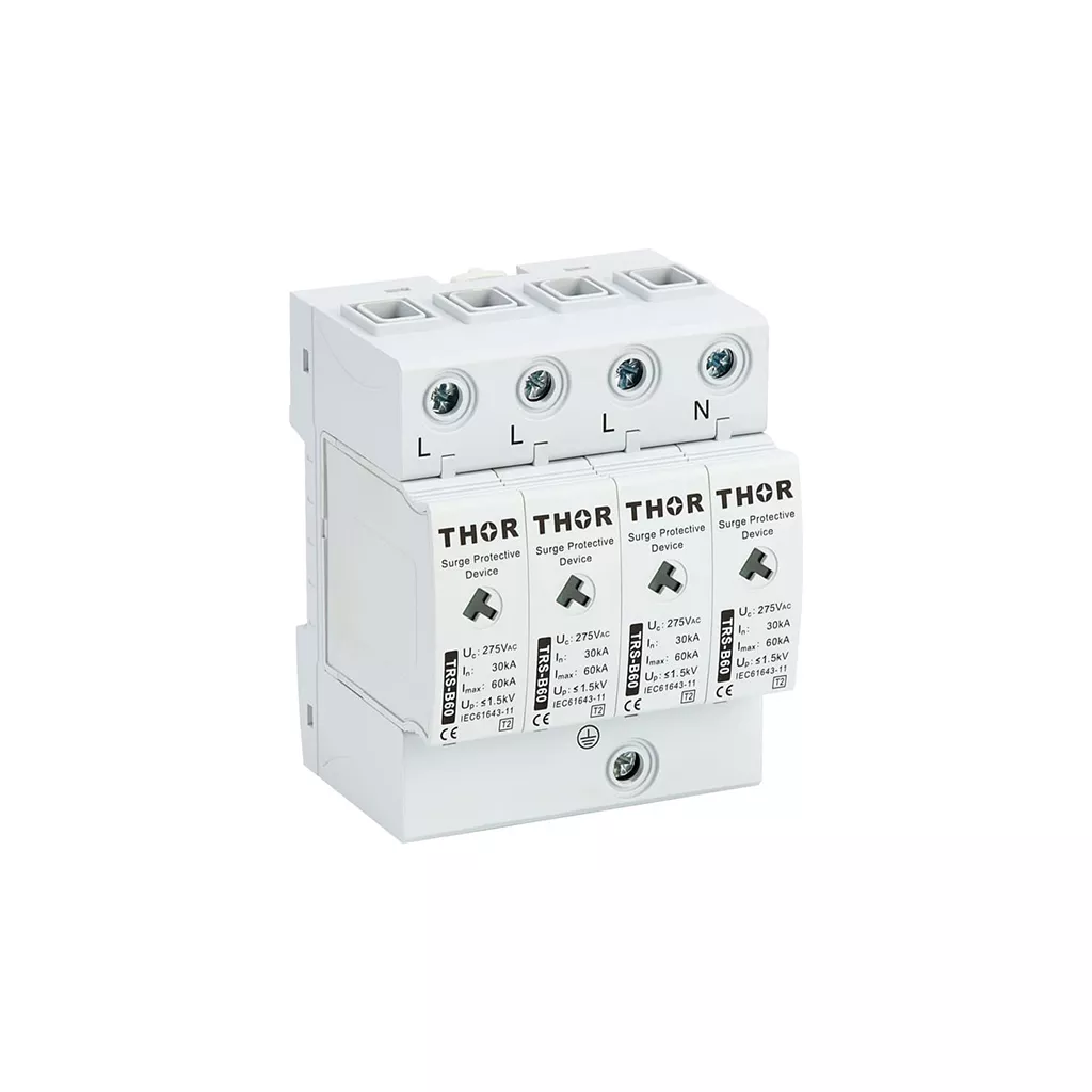
Figure 3. Thor Electric TRS-B60 Type 2 three-phase surge protection device, In 30kA / Imax 60kA, IEC 61643-11 certified
For a building with no LPS and no direct lightning exposure, a Type 2 at the main distribution board and a second Type 2 or Type 3 at critical equipment panels covers the standard protection cascade. Where an LPS is present, start with Type 1 or Type 1+2 at the service entrance. Thor Electric’s full range of AC surge protection devices covers all three types in both 230V and 380V configurations.
Where several protection stages are installed, the devices must work as a system; the SPD coordination guide explains energy sharing, protective-level grading and separation distance.
How Earthing System Determines Wiring Mode
Earthing system type is the single most important variable in three-phase SPD configuration. Fitting a 4-pole 3+1 device into a TN-C system, for example, creates a fault path rather than a protection path. The table below maps each earthing arrangement to the correct pole count and wiring mode.
| Earthing system | Wiring mode | Pole count | Protection type |
| TN-S | 3+1 (L1/L2/L3 + N → PE) | 4P | Common-mode + differential-mode |
| TT | 3+1 (L1/L2/L3 + N → PE) | 4P | Common-mode + differential-mode |
| TN-C | 3+0 (L1/L2/L3 → PEN) | 3P | Common-mode only |
| IT | 3+0 (L1/L2/L3 → PE) | 3P | Common-mode only |
Product labels are not always consistent across manufacturers. A 3P SPD normally protects L1, L2 and L3 without a separate neutral module. A 3P+N or four-pole assembly includes protection for the neutral path; in a 3+1 circuit, the three line-to-neutral elements are coordinated with a separate N-PE element. Confirm the internal circuit diagram instead of selecting by pole count alone.
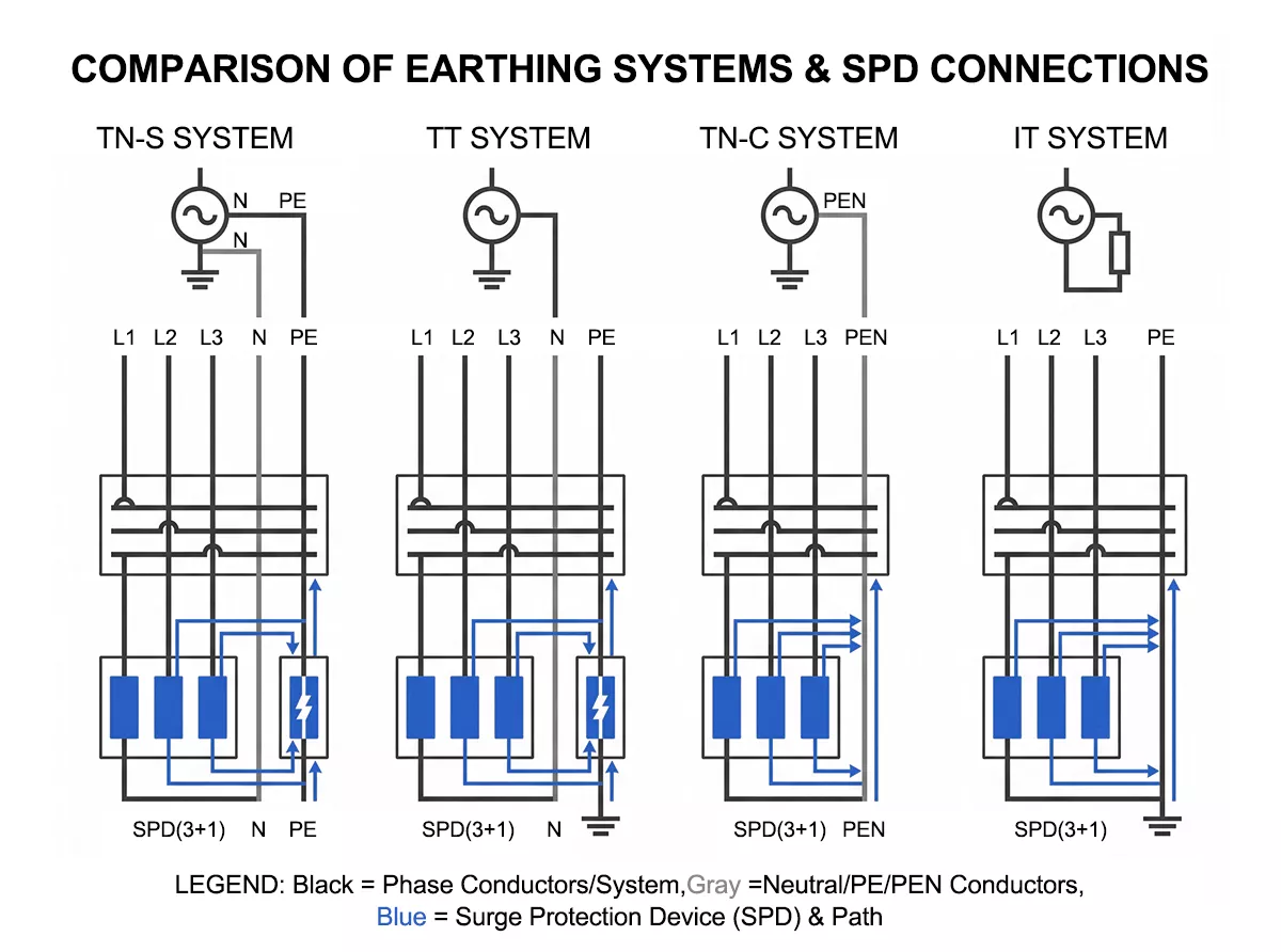
Figure 4. Three-phase SPD wiring mode by earthing system: TN-S and TT use 3+1 (4P); TN-C and IT use 3+0 (3P)
TN-S separates the neutral (N) and protective earth (PE) conductors throughout the installation. Surges travel L-N as well as L-PE, so the SPD covers both paths in 3+1 mode. For the structural detail of how TN-S earthing is arranged, see the TN-S earthing system guide.
TT systems also separate N and PE and use the same 3+1 configuration for the same reason — both differential-mode and common-mode surge paths are present.
TN-C merges neutral and protective earth into a single PEN conductor. There is no separate N terminal to connect — fitting a 3+1 SPD here would short the N-PE protection element across a conductor already at earth potential, either tripping the device immediately or damaging the N-PE element. A 3-pole device connecting L1, L2, L3 to PEN is the correct fit.
IT systems use a floating or impedance-earthed neutral. Line-to-neutral differential protection is not useful here because the neutral reference is not fixed relative to earth — applying L-N protection in an IT system can interfere with the insulation monitoring that these systems rely on to detect the first earth fault. A 3-pole L-to-PE arrangement covers the common-mode path without that interference.
The 4+0 vs 3+1 configuration in SPDs article covers the internal protection topology differences between these modes in more detail.
Choosing Uc, In and Imax
Three parameters drive SPD selection once type and wiring mode are confirmed: maximum continuous operating voltage (Uc), nominal discharge current (In), and maximum discharge current (Imax).
Maximum Continuous Operating Voltage (Uc)
Uc must exceed the highest continuous voltage the SPD will see across its protected mode. IEC 61643-11 Clause 6.5 lists standard rated values (255V, 275V, 320V, 385V, 440V AC and others); the selection is made from this table, not from a fixed multiplier formula.
For L-N and L-PE modes in a 230/400V TN-S or TT system, 275V AC is the standard choice — it sits above the nominal 230V phase-to-neutral voltage and absorbs the tolerance band without the SPD conducting continuously. Systems where grid voltage runs persistently above 230V warrant Uc 320V to avoid premature MOV degradation.
For 380V nominal (Un) industrial systems, the phase-to-neutral voltage is 220V but the line-to-line voltage is 380V. The TRS7 and TRS9 series are rated at Uc 385V AC for this configuration.
| System | Mode | Recommended Uc |
| 230/400V TN-S or TT | L-N / L-PE | 275V AC |
| 230/400V, high grid tolerance | L-N / L-PE | 320V AC |
| 380/660V industrial | L-N / L-PE | 385V AC |
| Any system | L-L | 440V AC |
Nominal and Maximum Discharge Current (In / Imax)
In is the current the SPD can handle repeatedly at the 8/20µs waveform without degradation. Imax is the single-event peak the device survives. For most industrial distribution boards, a Type 2 device rated In 20kA / Imax 40kA — the TRS-C40 — covers standard exposure. Main panels serving large industrial sites or installations in high-keraunic areas move up to Imax 60kA (TRS-B60) or 80kA (TRS-B80).
| Application | Recommended model | In | Imax |
| Sub-panel, light commercial | TRS-D20 | 10kA | 20kA |
| Distribution board, standard industrial | TRS-C40 | 20kA | 40kA |
| Main panel, heavy industrial | TRS-B60 | 30kA | 60kA |
| Main panel, high-lightning exposure | TRS-B80 / TRS-B100 | 40–60kA | 80–100kA |
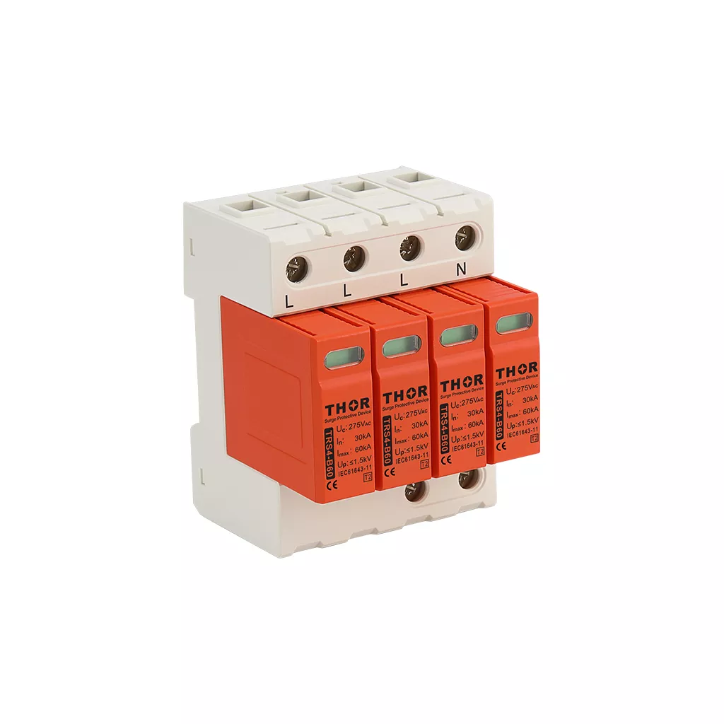
Figure 5: Thor Electric TRS4-B60 Type 2 three-phase surge protection device, In 30kA / Imax 60kA, IEC 61643-11 certified
Voltage Protection Level (Up)
Up is the peak voltage that passes through the SPD to downstream equipment during a surge. For Category III equipment — distribution boards, switchgear, industrial control panels — the impulse withstand voltage per IEC 60364-4-44 is 2.5kV. The SPD’s Up must stay below that threshold. TRS-D and TRS-C series devices achieve Up ≤1.0kV and ≤1.5kV respectively, well within the Category III limit. Installed Up rises with lead length — which is why the 50cm rule in the next section matters.
Wiring a 3-Phase SPD: Key Installation Rules
The SPD’s datasheet Up is measured under lab conditions with negligible lead length. Every centimetre of conductor between the SPD terminals and the busbar adds inductance, and that inductance raises the voltage reaching downstream equipment during a surge. A total lead length of 0.5m can add 0.5–1kV to the installed Up; at 1m, a device rated Up 1.5kV can deliver over 2.5kV to the load — pushing past the Category III withstand limit.
The 50cm rule: Keep the total path length — SPD live terminal to busbar, plus SPD PE terminal to earth busbar — at or below 50cm. Where panel geometry makes this difficult, reposition the SPD closer to the busbars or use a V-shaped wiring layout to shorten both conductors simultaneously.
Conductor cross-section: Minimum 6mm² for Type 2 connections per IEC 61643-12 application guidance; 16mm² for Type 1 and Type 1+2.
Upstream MCB: Install a MCB between the busbar and the SPD. For Type 2 devices, a 32–63A MCB sized to the SPD’s short-circuit current rating is standard. The MCB protects the installation if the SPD’s thermal disconnector fails under an extreme surge — not a routine event, but the reason IEC practice treats the upstream breaker as mandatory rather than optional.
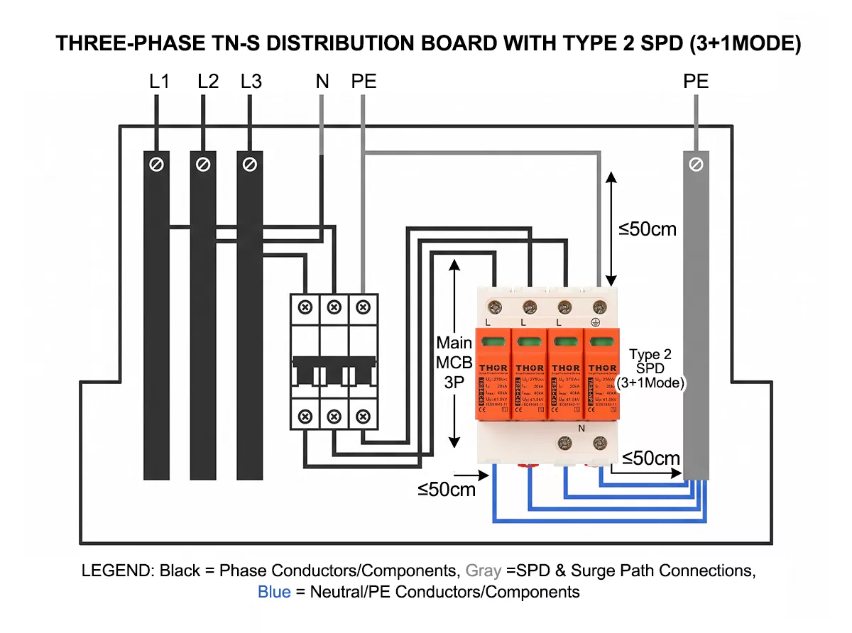
Figure 6. Type 2 three-phase SPD installation in a TN-S distribution board: 4-pole 3+1 wiring, upstream MCB, lead length ≤50cm from terminals to busbars
Symmetrical wiring: Keep the conductor lengths from each phase terminal to the SPD as equal as possible. Asymmetric lead lengths create unequal impedance between phases, meaning one phase will see a higher installed Up than the others during a surge.
Separation distance for cascaded devices: If a Type 1 and Type 2 are installed as separate devices, IEC 61643-12 recommends at least 10m of cable between them to provide the inductance needed for coordination. Without that separation, both devices conduct simultaneously and energy-sharing between them is unpredictable. Where 10m is not available, use a Type 1+2 combined device instead.
For complete wiring diagrams covering single-phase, three-phase and solar DC configurations by earthing system, see the SPD wiring diagram guide.
FAQ
What is the difference between a 3-phase and single-phase surge protection device?
A single-phase SPD protects one conductor pair — typically L-N or L-PE. A 3-phase surge protection device covers all three live conductors simultaneously, plus the neutral where the earthing system requires it. Three-phase systems carry surges along L-L, L-N, and L/N-PE paths at the same time; a single-phase device on one phase leaves the other two unprotected.
How do I choose Uc for a 3-phase SPD in a 230/400V system?
For L-N and L-PE modes in a standard 230/400V TN-S or TT system, select Uc 275V AC — the value that sits above nominal 230V phase-to-neutral voltage with adequate margin. Systems where grid voltage runs persistently high should use Uc 320V to avoid premature MOV degradation. IEC 61643-11 Clause 6.5 lists the standard rated values; selection comes from that table, not a fixed multiplier formula.
Does a 3-phase surge protection device need 3 poles or 4 poles?
It depends on the earthing system. TN-S and TT systems require a 4-pole device wired in 3+1 mode — three live conductors plus neutral, all referenced to PE. TN-C systems use a 3-pole device connecting L1, L2, L3 to the PEN conductor. IT systems also use 3-pole L-to-PE protection, with no N-PE stage. See the 4+0 vs 3+1 configuration in SPDs for the internal topology differences.
Can I use a Type 2 SPD at the main distribution panel in a three-phase system?
Yes, if the building has no external lightning protection system and no direct lightning exposure at the service entrance. In that case a Type 2 at the main panel covers induced lightning surges and internal switching transients. If an LPS is present, the service entrance requires a Type 1 or Type 1+2 — a Type 2 alone cannot survive the partial lightning current that flows back through the bonding conductor during a direct strike on the LPS.
How often should a 3-phase SPD be inspected or replaced?
Check the status indicator window after any known surge event and as part of routine panel maintenance — typically every 6–12 months. A red or failed indicator means the MOV elements have degraded and the device no longer protects. Pluggable module designs allow field replacement without rewiring. For a full inspection and replacement schedule, see the SPD maintenance guide.
Thor Electric Three-Phase SPDs
Thor Electric manufactures Type 1, Type 2, and Type 1+2 three-phase surge protection devices certified to IEC 61643-11, with TUV, CE, RoHS and CB certification. Models span Imax 10kA to 150kA across 230V and 380V nominal systems, with pluggable modules, remote signalling contacts, and OEM configurations available. Contact us to discuss panel specifications or request samples.