
Understanding the lightning arrester vs surge arrester distinction comes down to threat type: direct strike versus induced overvoltage. A lightning arrester intercepts direct lightning strikes at the building exterior. A surge arrester — also called a surge protective device (SPD) — clamps induced transient overvoltages inside the electrical distribution system. The two devices protect against different threats, operate to different standards, and cannot substitute for each other. Under IEC 62305-4, when an external lightning protection system is installed, surge arresters at the service entrance are a mandatory requirement.
What Is a Lightning Arrester?
A lightning arrester vs surge arrester comparison starts with location and threat. A lightning arrester sits outside on the roof, intercepting direct strikes of 20–200 kA (10/350 µs waveform) per IEC 62305-3 . A surge arrester sits inside the electrical panel, clamping induced transient overvoltages of a few kV to over 10 kV (8/20 µs waveform) per IEC 61643-11. Neither replaces the other.
A lightning arrester is an external device mounted at the highest point of a structure. Its job is to intercept direct lightning strikes and provide a low-resistance path for the lightning current to discharge safely into the ground — before it can damage the building structure or anything inside it.
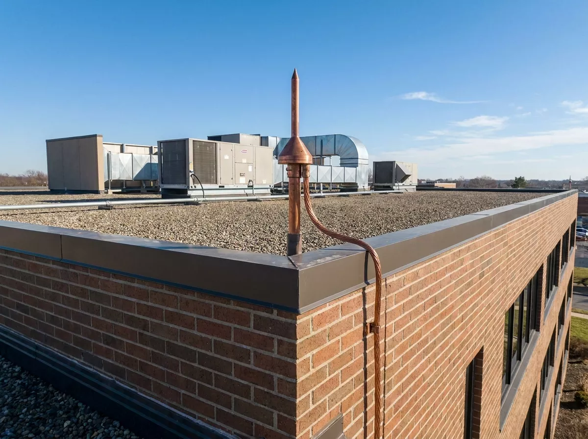
Figure 1 – A lightning arrester (air terminal) installed on a commercial rooftop — the first line of defense against direct strikes per IEC 62305-3
The complete system consists of three components: an air terminal (the pointed rod that captures the strike), a down conductor (the cable carrying the current to ground), and a grounding electrode (the buried component that disperses the energy). Together these form the Lightning Protection System (LPS), governed by IEC 62305-3.
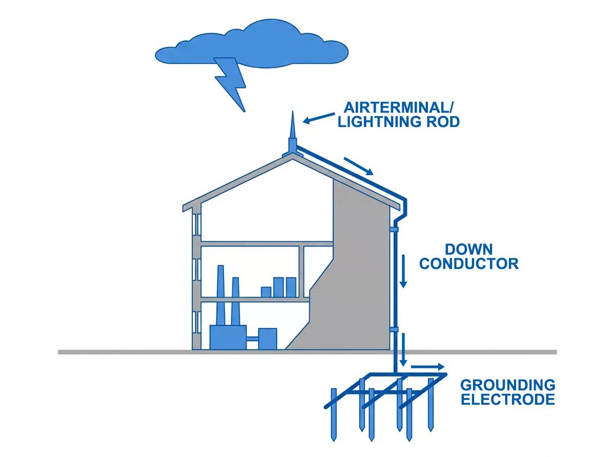
Figure 2 – External lightning protection system — air terminal, down conductor and grounding electrode per IEC 62305-3
Two types of air terminals are in common use:
Franklin rod (conventional air terminal) — a simple copper or aluminium rod placed at the building’s highest point. One rod covers a limited zone; larger structures need multiple rods with additional down conductors.
ESE lightning arrester (Early Streamer Emission) — an active air terminal that generates an upward leader earlier than a conventional rod, extending the effective capture radius. A single ESE device can protect the same footprint as several Franklin rods, making it the practical choice for large industrial facilities, warehouses, and telecom towers.
alt text: Franklin rod vs ESE lightning arrester protection radius comparison IEC 62305-3
A direct lightning strike delivers 20–200 kA of current in a 10/350 µs waveform. The grounding system must present a resistance below 10 Ω to dissipate that energy without creating dangerous step potentials around the building perimeter.
What Is a Surge Arrester?
In low-voltage building protection, surge arrester and SPD (Surge Protective Device) mean the same thing — an internal device installed inside electrical distribution panels, rated to IEC 61643-11. The term “surge arrester” also appears in power transmission contexts, where it refers to high-voltage devices rated 3 kV to 1,000 kV (IEC 60099-4) installed on overhead lines and transformers. This article covers low-voltage building SPDs only. For a broader introduction to SPD types and their role in electrical systems, see our guide to what is SPD in electrical ().
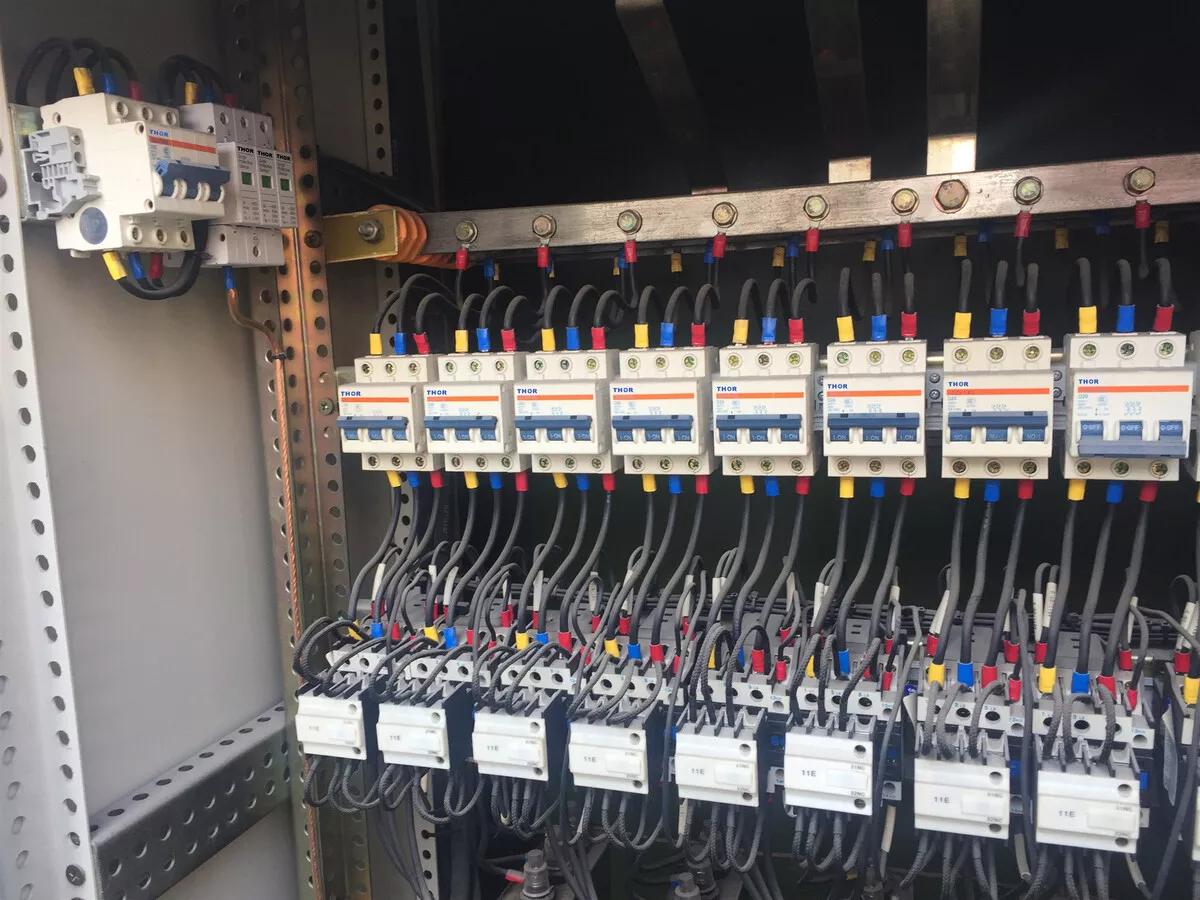
Figure 3 – Thor Electric surge arrester installed in a live industrial distribution board — field deployment, not a staged demo
A surge arrester clamps transient overvoltages — brief but intense voltage spikes caused by nearby lightning strikes, utility grid switching, motor startups, and capacitor bank operations. These spikes travel through the power wiring and reach connected equipment within microseconds. Without a surge arrester in the distribution panel, the spike hits the equipment directly.
The core component is the Metal Oxide Varistor (MOV) — a zinc oxide-based resistor whose impedance drops sharply when voltage exceeds the clamping threshold:
- Normal operation: MOV presents high impedance (>1 MΩ), invisible to the circuit
- Surge event: Voltage exceeds clamping threshold → MOV drops to low impedance (<10 Ω) within nanoseconds → surge current diverts to protective earth (PE)
- Post-surge: MOV resets to high impedance, ready for the next event
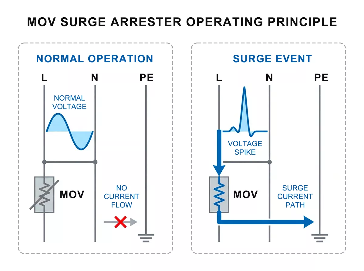
Figure 4 – Metal oxide varistor (MOV) operating principle in a surge arrester — high impedance at normal voltage, low impedance during surge
The key performance parameter is Up (voltage protection level) — the residual voltage that passes through to equipment during a clamping event. For Type 2 SPDs, Up is typically 1.0–2.0 kV depending on the model.
IEC 61643-11 classifies surge arresters into three types based on test waveform and installation point:
| Type | Test Waveform | Impulse Current | Installation Point |
| Type 1 | 10/350 µs | Iimp ≥ 12.5 kA/pole | Main service entrance |
| Type 2 | 8/20 µs | In 20–40 kA | Sub-distribution panels |
| Type 3 | 8/20 µs | Imax 5–10 kA | Equipment terminals |
| Type 1+2 | Both | Iimp ≥ 12.5 kA | Main service entrance (space-saving) |
The 10/350 µs waveform used to test Type 1 surge arresters matches the shape of partial lightning current — which is why Type 1 is the device required at the boundary where lightning current can enter the building. Type 2 uses the 8/20 µs waveform, which represents the attenuated surge after the Type 1 has absorbed the initial peak.

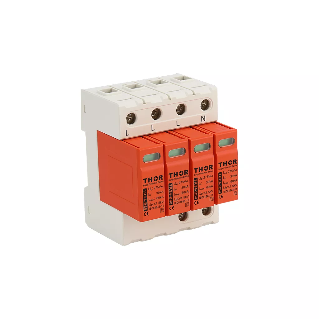
Figure 5 – Thor Electric TRS-A series Type 1 surge arrester (left) and TRS-B series Type 2 surge arrester (right), IEC 61643-11 certified
Lightning Arrester vs Surge Arrester: Key Differences
The confusion between these two devices is common — even among experienced engineers. The table below covers the fundamental differences.
| Lightning Arrester | Surge Arrester (SPD) | |
| Threat handled | Direct lightning strike (20–200 kA, 10/350 µs) | Induced transient overvoltage (few kV to 10 kV+, 8/20 µs) |
| Installation location | External — rooftop, building perimeter, transmission towers | Internal — main panel, sub-distribution boards, equipment cabinets |
| Protects | Building structure | Electrical equipment and connected devices |
| Governing standard | IEC 62305-3 | IEC 61643-11 (AC); IEC 61643-31 (DC/PV) |
| Can one replace the other? | No — different threats, different physics | No — IEC 62305-4 mandates both together |
One point that often gets missed: a lightning arrester does not protect electrical equipment, and a surge arrester cannot stop a direct strike. The energy of a direct lightning strike — up to 200 kA at 10/350 µs — is more than ten times the rating of a standard Type 2 surge arrester. Connecting a surge arrester where a lightning arrester is needed would destroy the SPD instantly.
The reverse is equally true. A lightning arrester diverts the direct strike current to ground, but does nothing about the electromagnetic field the strike generates around the down conductor. That field induces transient overvoltages of several kV to over 10 kV on every electrical cable inside the building — and those voltages travel straight to connected equipment. Only a surge arrester can clamp them.
As shown in Figure 6, the two devices protect against different threats at different points in the system.
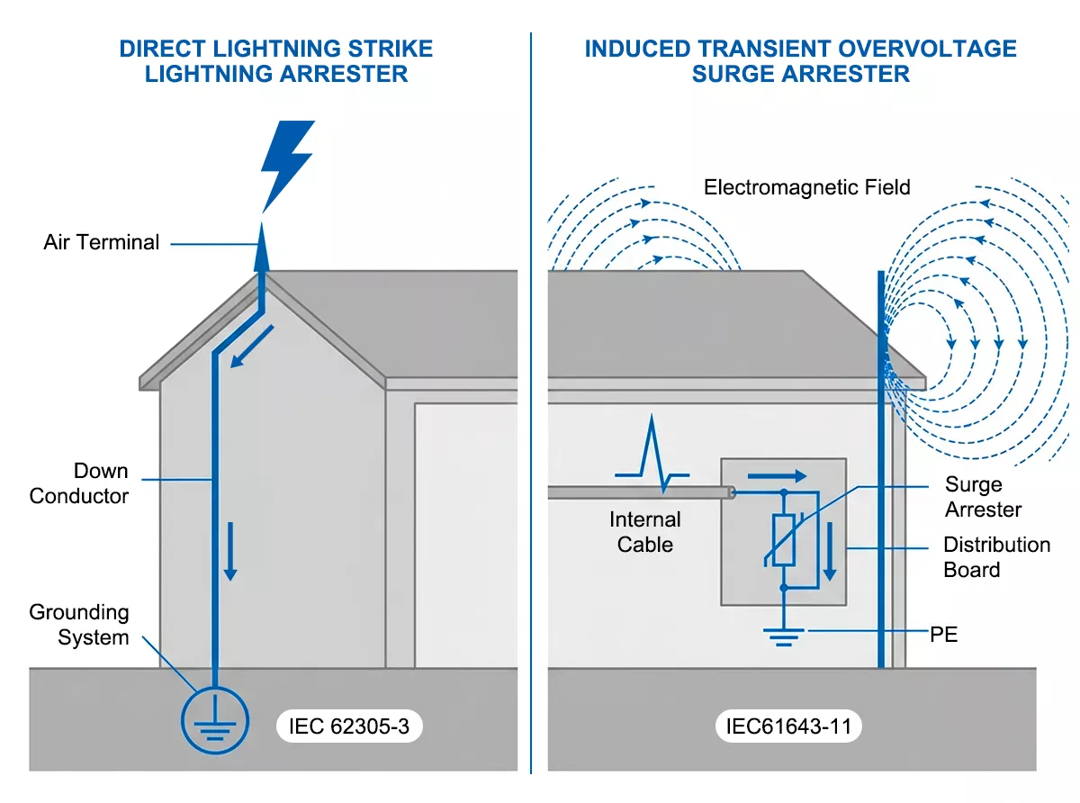
Figure 6 – Lightning arrester vs surge arrester — direct strike path handled externally, induced overvoltage path handled internally
Why a Lightning Arrester Alone Is Not Enough
Installing an external lightning protection system and stopping there is one of the most common — and costly — mistakes in electrical protection design.
Here is what actually happens when lightning strikes a building with a correctly installed LPS. The air terminal captures the strike. The down conductor carries 20–200 kA to the grounding electrode. The building structure is protected. So far, so good.
What the lightning arrester cannot control is the electromagnetic field that the rapidly changing current generates around the down conductor during discharge. That field couples inductively into every electrical cable running inside the building — power wiring, signal cables, data lines. The result is a transient overvoltage of several kV to over 10 kV propagating through the internal electrical system, reaching every connected device within microseconds. The PLC, the VFD, the SCADA module, the inverter — none of them are rated for that.
IEC 62305-4 accounts for this directly. The standard divides the protected space into Lightning Protection Zones (LPZ), and defines which protective measures are required at each zone boundary.
Figure 7 illustrates how IEC 62305-4 divides the protected space into Lightning Protection Zones, with surge arresters required at each boundary.
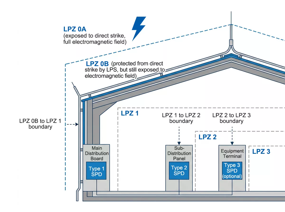
Figure 7 – IEC 62305-4 Lightning Protection Zones — LPZ 0A/0B outside, LPZ 1 at service entrance, LPZ 2 at sub-distribution, surge arresters required at each boundary
The four zones relevant to building electrical protection:
- LPZ 0A — outside the building, directly exposed to lightning strikes and the full unattenuated electromagnetic field
- LPZ 0B — outside but shielded from direct strikes by the LPS air terminal; still exposed to the electromagnetic field and partial lightning current
- LPZ 1 — inside the building at the main distribution board level; direct strike current excluded, but induced surges still present
- LPZ 2 — deeper inside, at sub-distribution panel level; further attenuation of residual surges
At the LPZ 0B→1 boundary — the main service entrance — IEC 62305-4 requires a Type 1 surge arrester rated for partial lightning current (10/350 µs waveform). This is a normative requirement: the standard uses “shall,” not “should.” At the LPZ 1→2 boundary, a Type 2 surge arrester handles the attenuated residual surge.
The Iimp requirement at the LPZ 0B→1 boundary depends on the Lightning Protection Level (LPL) of the building:
| Lightning Protection Level | Minimum Iimp per pole (Type 1 SPD) |
| LPL III / IV | 12.5 kA |
| LPL II | 18.75 kA |
| LPL I | 25 kA |
For most industrial facilities — which typically fall under LPL I or II — TRS-A25 (Iimp 25 kA, Up ≤2.2 kV) is the appropriate choice at the service entrance. TRS-A15 (Iimp 15 kA, Up ≤2.0 kV) covers LPL III/IV installations where a lower protection level has been confirmed by risk assessment.
Selecting the Right Protection for Your Installation
The lightning arrester vs surge arrester question is not an either/or decision — it is a sequencing question. Start with the external threat, then work inward.
Step 1 — Determine whether an external LPS is required
Run an IEC 62305-2 risk assessment. The key inputs are building height, construction type, location, keraunic level (thunderstorm days per year), and consequence of failure. Most commercial and industrial facilities in regions with more than 25 thunderstorm days per year will exceed the tolerable risk threshold and require an external LPS.
If the risk assessment confirms an external LPS is needed, a Type 1 surge arrester at the service entrance becomes mandatory under IEC 62305-4 — not optional.
Step 2 — Select the Type 1 surge arrester based on Lightning Protection Level
The LPL is determined by the risk assessment output. For most industrial facilities:
- LPL I or II — specify TRS-A25 (Iimp 25 kA, Up ≤2.2 kV). Covers the 25 kA/pole requirement for LPL I and the 18.75 kA/pole requirement for LPL II.
- LPL III or IV — TRS-A15 (Iimp 15 kA, Up ≤2.0 kV) meets the 12.5 kA/pole minimum. TRS-A25 remains the conservative choice where budget allows.
Both models use graphite gap technology, respond in under 100 ns, and are certified to IEC 61643-11 Type 1.
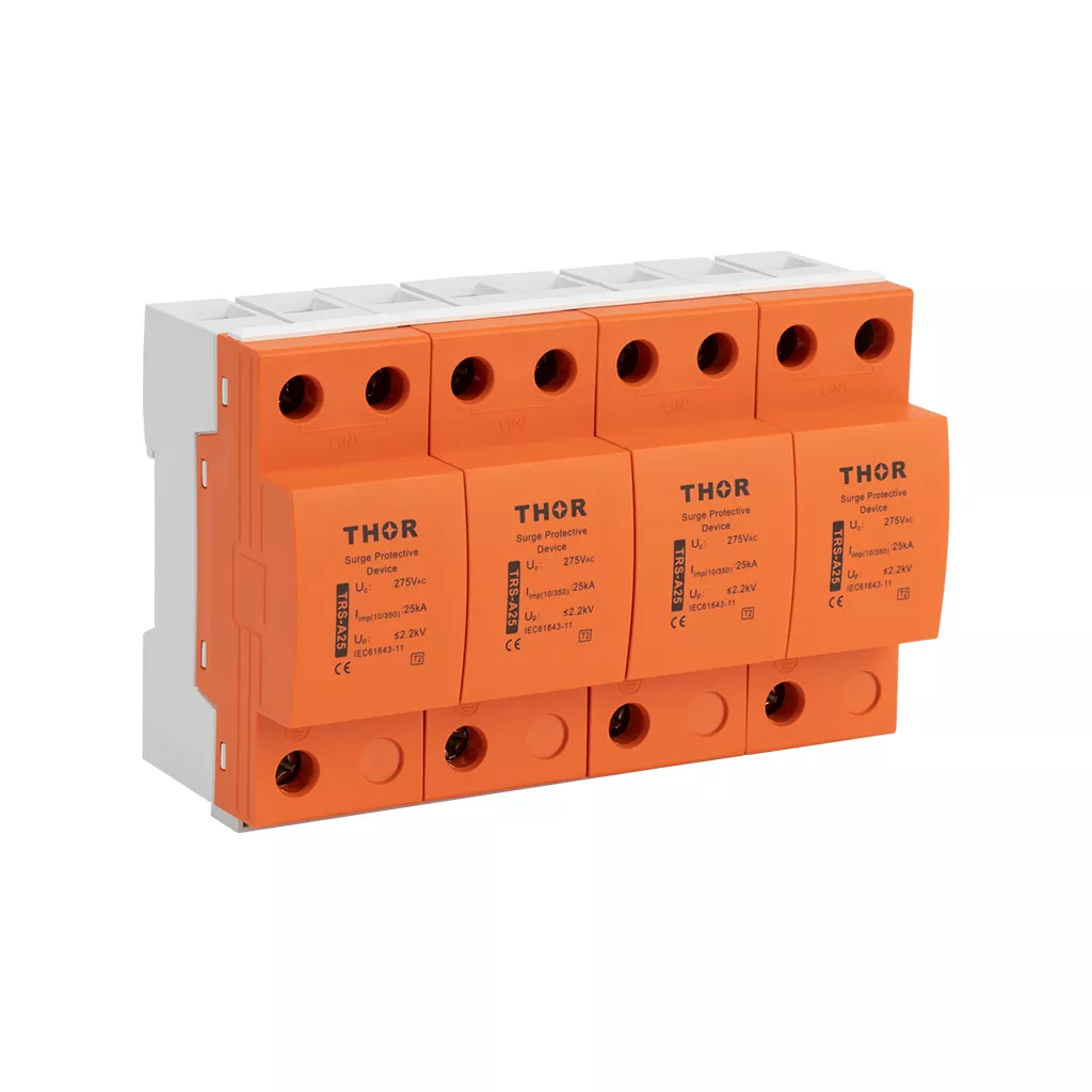
Figure 8 – Thor Electric TRS-A25 Type 1 surge arrester, Iimp 25 kA, graphite gap technology, IEC 61643-11 certified
Step 3 — Add Type 2 surge arresters at sub-distribution panels
A Type 1 alone is not sufficient. The residual surge energy after the Type 1 clamps the initial peak still propagates through the system and can damage equipment at sub-distribution level. A Type 2 surge arrester at each sub-panel absorbs this residual.
For standard three-phase industrial distribution boards, TRS-B60 (In 30 kA, Imax 60 kA, Up ≤1.8 kV) is a practical starting point. Higher-demand installations — motor control centres, VFD panels, SCADA cabinets — benefit from TRS-B80 or TRS-B100.
Step 4 — Consider Type 1+2 where panel space is limited
Where a separate Type 1 and Type 2 cascade is not practical — small panels, retrofit installations, single-phase systems — a Type 1+2 combination unit handles both protection levels in one device. The TRS5-B+C covers Iimp 12.5 kA and Imax 50 kA in a single DIN rail module, suitable for LPL III/IV installations.
No external LPS — does a surge arrester still make sense?
Yes. Even without a direct strike on the building, nearby lightning within 1–2 km induces transient overvoltages on the utility power lines feeding the site. Those surges travel into the building through the supply cable. A Type 2 surge arrester at the main distribution board protects against this regardless of whether an external LPS is present.
For buildings without an external LPS in high keraunic zones, a Type 1+2 combination unit at the service entrance covers both scenarios — partial lightning current from a nearby strike on the supply line, and standard switching transients.
FAQ
Is a lightning arrester the same as a surge arrester?
No. A lightning arrester is an external device — air terminal, down conductor, and grounding electrode — that intercepts direct lightning strikes and routes the current safely to ground. A surge arrester (SPD) is an internal device installed inside electrical panels that clamps induced transient overvoltages from lightning, switching events, and grid faults. The two devices protect against completely different threats and cannot replace each other.
What is the difference between lightning and surge?
A lightning strike is a direct discharge of 20–200 kA between a storm cloud and a structure, delivered in a 10/350 µs waveform. A surge (transient overvoltage) is a brief voltage spike of a few kV to over 10 kV on the electrical wiring, typically caused by electromagnetic induction from a nearby lightning strike, utility grid switching, or large motor startups. A direct lightning strike on the building requires a lightning arrester. The surges that result from it — and from all other sources — require a surge arrester.
What is the purpose of a surge arrester?
A surge arrester clamps transient overvoltages before they reach and damage connected electrical equipment. When voltage exceeds the clamping threshold, the MOV inside the surge arrester switches from high impedance to low impedance within nanoseconds, diverting the surge current to protective earth. After the transient passes, the MOV resets and the device continues monitoring. For more on how the core component works, see our guide to metal oxide varistors (MOV) .
What is the difference between an SPD and a lightning arrester?
SPD (Surge Protective Device) is the IEC 61643-11 term for what is commonly called a surge arrester in low-voltage building protection. The distinction from a lightning arrester is the same: SPD = internal panel device protecting equipment from surges; lightning arrester = external structural device protecting the building from direct strikes. One point of terminology confusion: “lightning surge arrester” sometimes refers to a Type 1 SPD — an internal device rated for partial lightning current at the service entrance. This is not the same as an external lightning arrester.
Do I need both a lightning arrester and a surge arrester?
If your facility has an external lightning protection system, yes — IEC 62305-4 makes SPD installation at the service entrance a normative requirement, not a recommendation. Even without an external LPS, a surge arrester is still needed: nearby lightning induces transient overvoltages on the utility supply lines that reach your equipment regardless of whether the building has a lightning rod. For a detailed look at how SPD types are classified, see our guide to Type 1 vs Type 2 vs Type 3 SPD .
How do I choose between a Type 1 and Type 2 surge arrester?
The choice depends on where the SPD is installed and whether an external lightning protection system is present. A Type 1 surge arrester is required at the main service entrance (LPZ 0B→1 boundary) when an external LPS is installed — it handles partial lightning current at the 10/350 µs waveform. A Type 2 surge arrester goes at sub-distribution panels (LPZ 1→2 boundary) to handle attenuated residual surges at the 8/20 µs waveform. When both are needed, a Type 1+2 combination unit can cover both functions in a single device.
Thor Electric SPDs for Lightning and Surge Protection
Thor Electric manufactures Type 1, Type 2, and Type 1+2 surge protective devices certified to IEC 61643-11, TUV, CE, RoHS, CB and ISO standards. The TRS-A series covers Type 1 from Iimp 15 kA to 50 kA per pole for LPL I–IV; TRS-B, TRS-C and TRS-D series cover Type 2 for single-phase and three-phase distribution boards with pluggable modules for field replacement. Samples and project-specific recommendations are available — contact us through our contact page for your installation requirements.