
IEC 60364 sorts a low-voltage installation by two questions: how the supply source is earthed, and how the exposed conductive parts of the installation are earthed. Those two answers give three families and five arrangements. On a normal public supply, the arrangement is declared by the network operator. A separately derived source, a defined part of an installation, or a TT installation used where no TN earth is available can all sit outside that default.
The five types of earthing systems are not interchangeable labels. The arrangement fixes the path a fault current takes back to its source. That path decides which fault-protection method clears the fault, and it constrains how a surge protective device can be connected.
How many types of earthing systems are there?
IEC 60364 defines three earthing system families: TN, TT and IT. The TN family divides into three arrangements, giving five in total: TN-S, TN-C, TN-C-S, TT and IT. Three and five are both correct answers at different levels. Three counts the families. Five counts the types of earthing systems an installation can actually have.
BS 7671 recognises the same five, which is the answer to a question people ask about the regulations specifically. Both counts circulate, and so does a third. Some summaries say four, which usually means TN-C has been dropped from the list. That omission is understandable in a UK context, because a PEN conductor is prohibited inside consumers’ installations in Great Britain. TN-C still exists in distribution networks and in installations outside Great Britain, so removing it makes the set of types of earthing systems look tidier than it is.
The classification comes from IEC 60364-1, which fixes the terminology used across every other part of the standard.
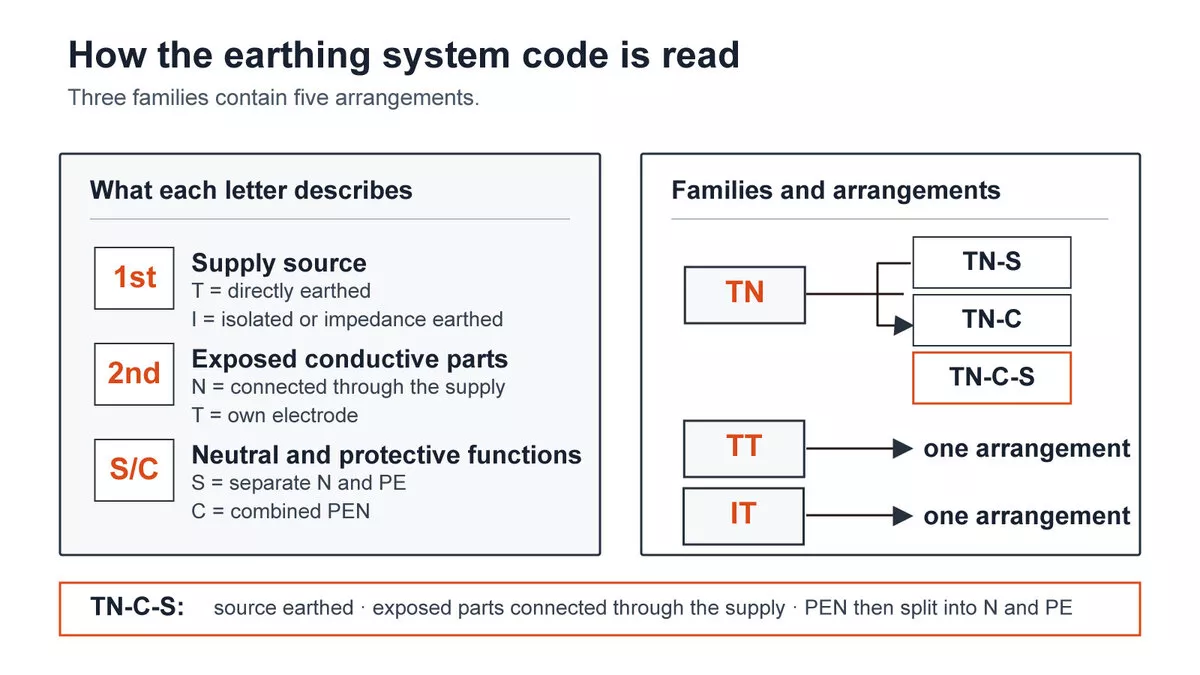
Figure 1 — How an earthing system code is read, and how three families give five arrangements.
Earthing or grounding: the same thing under two standards
The vocabulary is worth settling before the types of earthing systems get compared. IEC and British documents say earthing. IEEE and the American NEC say grounding. The two words name the same physical connection, and a document that uses one consistently is not describing a different practice from one that uses the other.
One distinction underneath the vocabulary does matter. System earthing is what the live conductors of the supply are referenced to, and it is what the TN, TT and IT codes describe. Equipment earthing is the connection from exposed metal parts to the protective conductor. A question about “the two types of grounding” is usually reaching for this split, not for a two-item version of the five arrangements.
The five types of earthing systems at a glance
| Arrangement | Where the PE comes from | N and PE combined anywhere | Where you meet it |
| TN-S | Network operator, separate protective conductor | No | Supplies with a separate earth conductor or cable sheath |
| TN-C | Network operator, combined PEN | Yes, throughout | Distribution networks; prohibited in GB consumers’ installations |
| TN-C-S | Network operator, PEN split at the origin | Yes, up to the split | The most common UK supply, distributed as PME |
| TT | The consumer’s own earth electrode | No | Rural and overhead supplies, sites with no TN earth available |
| IT | Nothing, or a high impedance at the source | No | Hospitals and processes that must not trip on a first fault |
In a TN-S earthing system, the neutral and protective conductors stay separate from the source all the way to the installation.
A TN-C-S earthing system runs a combined PEN conductor to the origin of the installation, then splits it into separate neutral and protective conductors. UK distributors supply it as PME, which is why the two names appear in the same conversation.
A TT earthing system has an earthed supply neutral, but the distributor does not supply the consumer’s protective earth. The consumer installs a local earth electrode, and the two earths are not bonded to each other.
TN-C uses one PEN conductor for both functions through the whole installation. Section seven covers where that is allowed.
IT either leaves the source unearthed or connects it to earth through a deliberately high impedance. A first insulation fault produces only a small current through the system capacitance or impedance, so the supply normally continues while the fault is located. Hospitals and continuous industrial processes use it for exactly that reason.
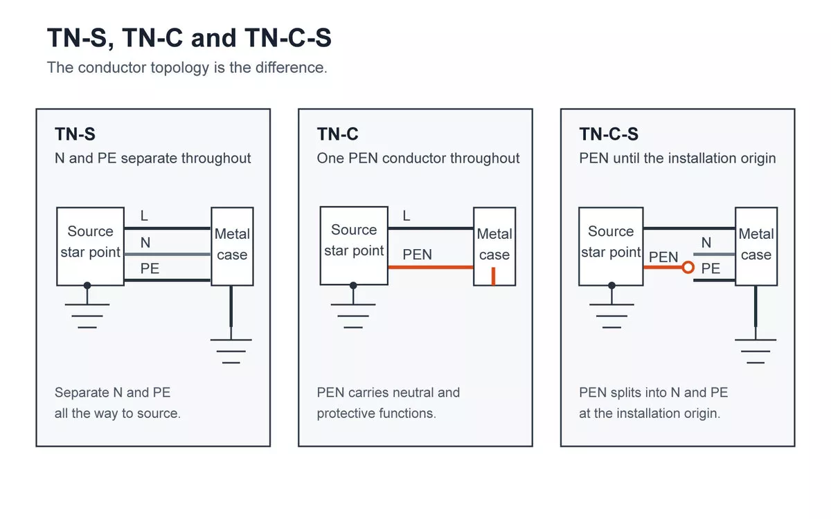
Figure 2 — TN-S, TN-C and TN-C-S: where the neutral and protective conductors separate.
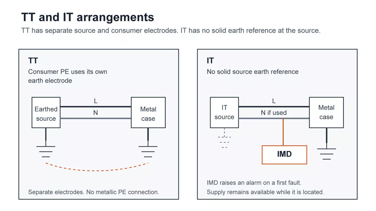
Figure 3 — TT and IT: an independent consumer electrode, and a supply with no solid earth reference.
Figures 2 and 3 draw all five on the same skeleton, so the only thing that moves between panels is the conductor topology.
What the letters actually mean
The codes are readable once you know that each position answers a fixed question, as Figure 1 sets out.
| Position | Letter | What it says |
| First | T | The supply source has a direct connection to earth |
| First | I | The supply is isolated from earth, or connected through a high impedance |
| Second | T | Exposed conductive parts go to their own local earth electrode |
| Second | N | Exposed conductive parts take their earth from the supply |
| Suffix | S | Neutral and protective functions run as separate conductors |
| Suffix | C | Neutral and protective functions are combined in one conductor |
Read TN-C-S with that rule and it decodes itself: earthed supply, installation earthed via the supply, combined first and separated afterwards. The same three questions decode all five types of earthing systems.
How the fault path differs, and why it changes the protection method
This is where the types of earthing systems stop being a naming exercise. An earth fault has to complete a circuit back to the source, and the arrangement decides what that circuit is made of.
In a TN system, the return path is metallic for its whole length, through the PE or PEN conductor. Impedance is low, fault current is high, and an overcurrent device sees enough current to operate within its required disconnection time.
In a TT system, the fault current leaves through the consumer’s electrode, passes through soil, and returns through the source electrode. Soil is a poor conductor and its resistance varies with moisture and season. TT installations therefore normally use a residual current device for fault protection; an overcurrent device can do the job only where the loop impedance is low enough to meet the required disconnection time.
In an IT system, system capacitance or the deliberate source impedance limits the first-fault current. Automatic disconnection normally does not occur, so an insulation monitoring device raises the alarm while the supply remains available. A second fault on another phase is the event that must then be cleared.
Figure 4 traces all three return paths on the same layout. BS 7671 tabulates the maximum earth fault loop impedance for each protective device and disconnection time. Those values are where a design gets verified; the comparison above is what tells you which verification applies.
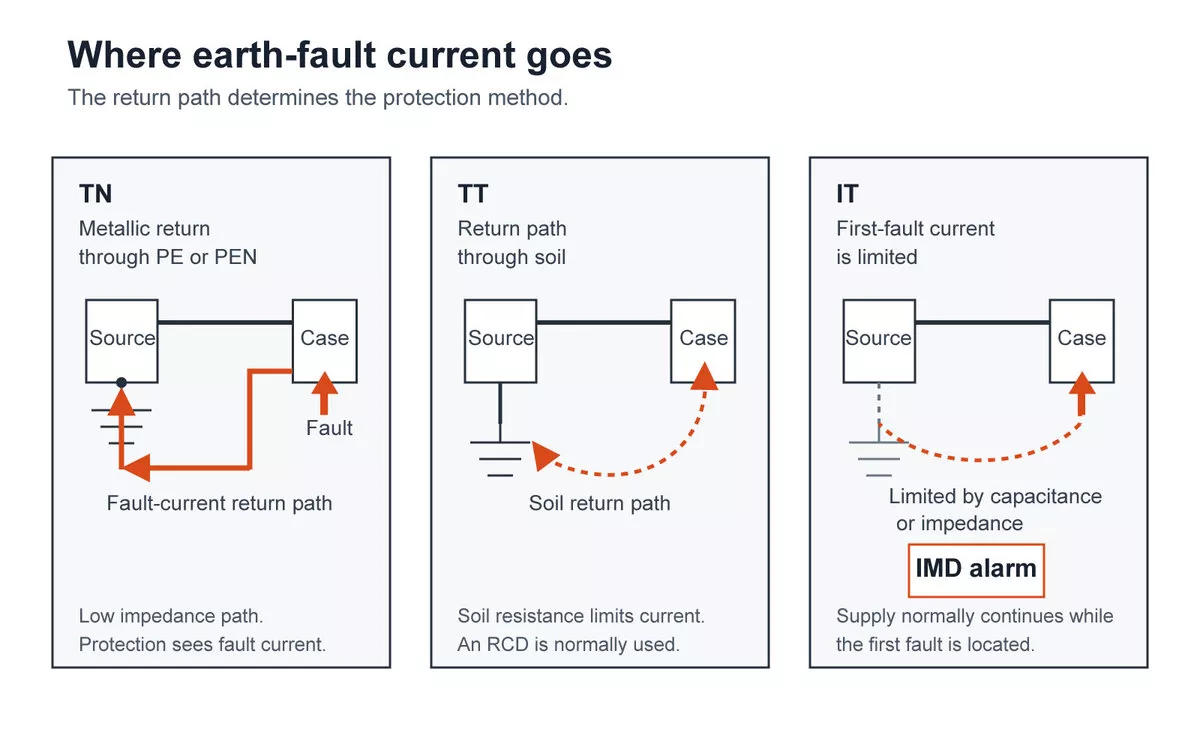
Figure 4 — Earth fault current path in TN, TT and IT systems.
What each of the types of earthing systems means for SPD connection
The same fault path that decides the protection method also constrains how a surge protective device is wired, and the types of earthing systems differ sharply here. The table below gives the connection schemes for each arrangement, and for TT it gives the condition that governs the choice.
| Arrangement and SPD position | Three-phase | Single-phase |
| TN-S | 3+1 (CT2) or 4+0 (CT1) | 1+1 (CT2) or 2+0 (CT1) |
| TN-C-S, downstream of the PEN split | Same as TN-S | Same as TN-S |
| TN-C-S, upstream of the split | Treat as TN-C | Treat as TN-C |
| TN-C | Line conductors to PEN | Line to PEN |
| TT, SPD upstream of the main RCD | 3+1 (CT2) | 1+1 (CT2) |
| TT, SPD downstream of an RCD | 4+0 (CT1) also applicable | 2+0 (CT1) also applicable |
| IT without a distributed neutral | 3+0 | 1+0 |
| IT with a distributed neutral | See IEC 61643-12 | See IEC 61643-12 |
Three of those rows need a sentence of explanation.
TN-C-S depends on where the device sits. IEC 61643-12 writes its connection guidance for TT, TN-C, TN-S and IT, with no separate TN-C-S category, because the answer changes at the PEN split. Downstream of the split the installation is TN-S, and almost every consumer distribution board is downstream. Upstream of it there is no separate protective conductor yet, so the TN-C row applies.
TN-S and the downstream part of TN-C-S can use either CT1 or CT2. The required protection modes, temporary-overvoltage behaviour and the SPD manufacturer’s approved wiring decide between them.
For TN-C itself, the line conductors connect to the PEN. There is no separate neutral-to-PE mode to protect, because the neutral and protective functions are the same conductor. That is a narrower statement than “nothing to connect”.
For TT, the RCD position governs the answer. Under IEC 60364-5-53, CT2 (3+1 on three-phase, 1+1 on single-phase) is required when the SPD is upstream of the main RCD, while CT1 (4+0 or 2+0) is applicable only downstream of an RCD. Confirm the RCD position and the coordination between devices before selecting an assembly. The reason the neutral-to-PE path gets separate treatment in TT is that IEC 61643-11 tests it harder there, at 1200 V AC between neutral and PE for 200 ms, which is a temporary overvoltage condition rather than a surge. The choice between the two connection types is covered in detail in 4+0 and 3+1 SPD configurations.
IT with a distributed neutral is the one case this article leaves open. The presence of a neutral changes the fault voltage that appears across the device, and the applicable scheme should come from IEC 61643-12 or from manufacturer data for the specific product, not from a general table.
Once the arrangement and the position are settled, the remaining selection work is device class and rating. Thor’s AC surge protection devices cover the Type 1 and Type 2 positions these schemes apply to.
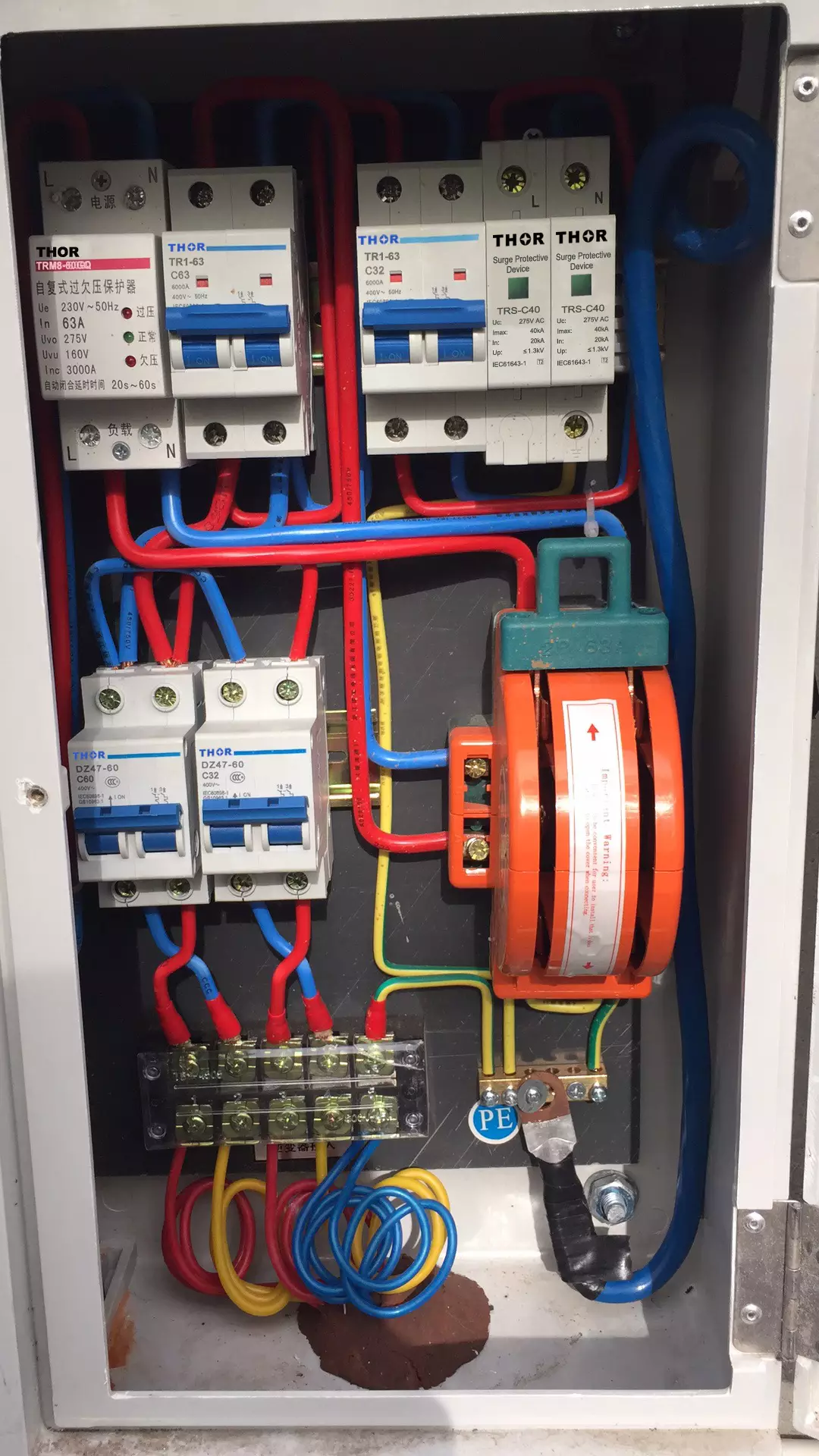
Figure 5 — Surge protective devices installed in a distribution board.
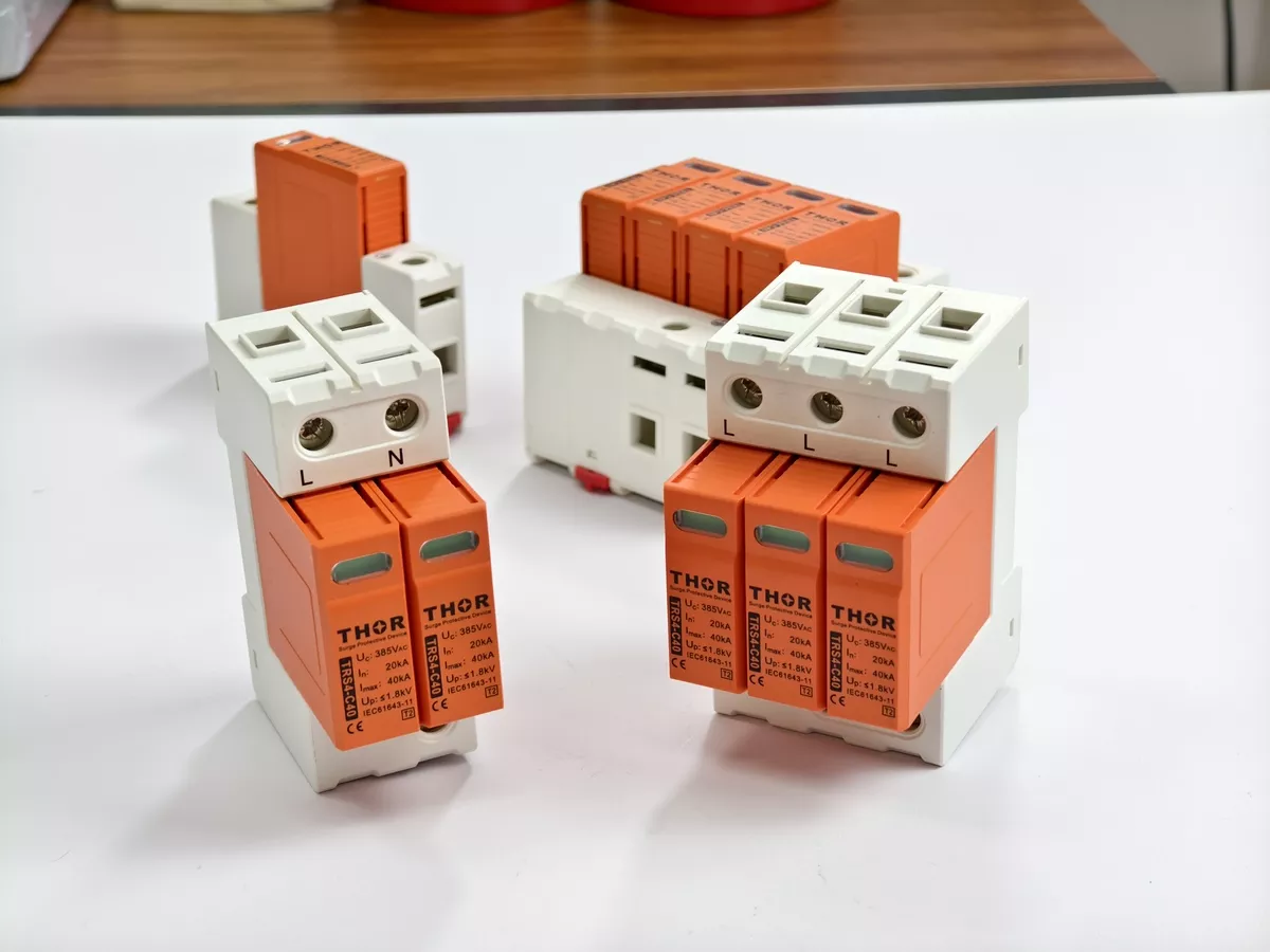
Figure 6 — Thor AC surge protective devices.
Why TN-C is not permitted in a consumer’s installation
Of the five types of earthing systems, TN-C is the one with a legal restriction attached, and the restriction has a specific source and a specific geography.
In Great Britain, Regulation 8(4) of the Electricity Safety, Quality and Continuity Regulations prohibits the use of a PEN conductor in a consumer’s installation. That is a statutory instrument. BS 7671 Regulation 543.4 sets out the requirements for PEN conductors and cross-references the prohibition, which makes it the installation-standard reference and not the legal source. Outside Great Britain, and within distribution networks, TN-C is not banned by IEC 60364 itself.
The hazard behind the rule is worth separating from the rule. A PEN conductor carries load current and is the protective conductor at the same time. If it fractures, neutral current can divert through bonded pipework or adjacent installations, and exposed metalwork can rise toward line voltage. That condition may not produce the overcurrent needed to trip ordinary protection. Figure 7 shows both states side by side. The IET’s broken PEN article covers the failure and its consequences for PME installations.
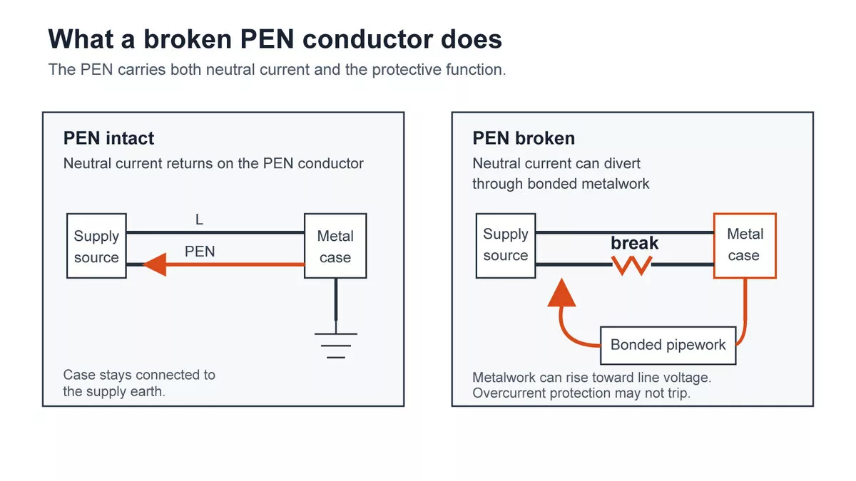
Figure 7 — A broken PEN conductor in a TN-C system raises exposed metal toward line voltage.
FAQ
Which of the types of earthing systems is used in most UK installations?
TN-C-S, distributed by network operators as PME. TT is common on rural and overhead supplies, and TN-S appears on older networks with a separate earth conductor.
Which earthing system is best for a home?
The question does not usually have an answer the homeowner controls. For a normal public supply the network operator declares the arrangement, and the installation is designed around it. What changes with the arrangement is the fault-protection method and the SPD connection scheme.
Can one installation have more than one earthing arrangement?
Yes. A separately derived source, such as a generator or an isolating transformer supplying a defined part of an installation, can establish a different arrangement downstream of it. The supply arrangement at the origin does not have to apply to every part of a site.
Does the earthing arrangement change which SPD type I need?
Not directly. Type 1, Type 2 and Type 3 follow from the lightning exposure and the position in the installation. The arrangement decides the connection scheme, which is a separate property from the type.