
A charge point fixed in place and connected by permanent wiring is an installation, so EV charger surge protection is governed by the IEC 60364 series. IEC 60364-7-722 sets the requirements for electric vehicle supply installations, and IEC 60364-4-44 clause 443 holds the assessment that decides whether surge protective devices are required for a given installation.
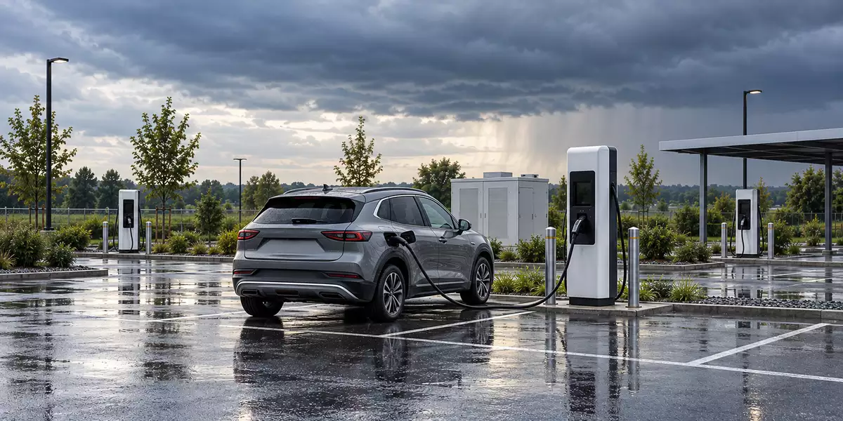
Figure 1 — EV charger surge protection in context: an outdoor charge point, connected vehicle and distribution equipment.
The harder question is the one the standards answer less directly: which class of device the exposure calls for, and what the device is bonded to. Most of the money spent on EV charger surge protection goes on the device, and a correctly rated SPD wired into an incomplete earthing arrangement will not hold the protection level printed on its datasheet.
What the standards require for EV charger surge protection
The requirement is spread across several parts of IEC 60364, which is the first irritating thing about the subject: no single clause tells you what to fit.
| Part | What it settles |
| IEC 60364-7-722 | Requirements for electric vehicle supply installations, including the surge protection provisions that apply to charging equipment |
| IEC 60364-4-44, clause 443 | Whether protection against transient overvoltages is required, from the consequence of a failure and the rated impulse withstand voltage of the equipment |
| IEC 60364-5-53, clause 534 | How the SPD is selected, positioned and connected once clause 443 calls for one |
| IEC 62305 | Applies additionally where a direct lightning strike to the structure or the supply is a credible risk |
Clause 443 works from consequence, not from equipment price. For EV charger surge protection, a failure that interrupts a public service is treated differently from one whose consequences are limited to a private installation. The general case for fitting protection is outside this EV-specific guide.
Read the operative clauses for the installation in front of you before treating any of this as settled. EV charger surge protection requirements differ between publicly accessible charging facilities and private ones, and the detail sits in the standard text rather than in a summary of it.
In the UK the same IEC requirements arrive through BS 7671, now at Amendment 4:2026, and installers meet them as a wiring regulation instead of as an IEC clause. Section 722 there carries requirements specific to electric vehicle charging, including protective measures tied to the supply earthing arrangement that sit outside the surge question entirely.
What actually reaches the charge point
Three mechanisms, not one. A direct or partial lightning current arrives as a 10/350 µs impulse and carries real energy. A strike some distance away couples into the supply and control wiring inductively and capacitively, producing an 8/20 µs impulse; induced surges remain damaging at distances of a kilometre or more. Switching transients come from the grid, from earth faults and short circuits, and from the charge point’s own contactors.
Charging adds one failure mode that a distribution board does not have. With a vehicle connected, a surge reaching the charge point has a path down the charging cable into the vehicle’s charge controller and battery management system. EV charger surge protection is therefore standing in front of an asset the operator does not own.
Choosing the SPD by the exposure at the charge point
The class of device follows the lightning protection zone that the charge point and its incoming conductors occupy. Not the charger’s power rating, and not whether it delivers AC or DC to the vehicle.
| Exposure to establish | Coupling to expect | Device class it points to |
| Equipment or any entering conductor lies outside a protected volume, so partial lightning current can be conducted in (LPZ 0A) | Galvanic coupling of partial lightning current, plus induced surges | Type 1+2 combined, coordinated with the terminal equipment |
| Equipment and all entering conductors lie inside a volume protected against direct strikes (LPZ 0B) | Induced and capacitive coupling only | Type 2, coordinated with the terminal equipment |
Figure 2 shows why EV charger surge protection selection has to cover both the charge point and its cable routes.
The table is the starting point for EV charger surge protection, not a lookup. Zone assignment is an assessment, not a description of what the installation looks like from the road, and four things have to be checked before the class is settled: whether the protected volume established by any lightning protection system actually contains the equipment, where the supply and data cables run and which zone boundaries they cross, what separation distance applies, and what protection already sits upstream. Zone boundaries are set out in full in the guide to the lightning protection zone concept, and the classes themselves in the difference between Type 1 and Type 2 SPDs.
Two cases show why the visual shortcut fails. A wallbox mounted on a protected building is often in LPZ 0B, but a supply cable that runs to it from a separate outbuilding can cross a zone boundary and bring a partial lightning current with it. A post under a canopy looks sheltered, yet the canopy only establishes LPZ 0B where its lightning protection system creates a protected volume that actually encloses the post.
Coordination is the second half of the answer. Published guidance for charging infrastructure recommends coordinated arrangements reaching the terminal equipment, so treat a single upstream device as one stage of EV charger surge protection and not as the whole concept. Where the charge point electronics need a lower let-through than the upstream SPD delivers, a coordinated downstream stage belongs in the design, with the stages matched to their lead lengths and protection levels.
Where the exposure cannot be assessed with confidence, the defensible default for EV charger surge protection is the combined Type 1+2 device, because it covers both coupling mechanisms.
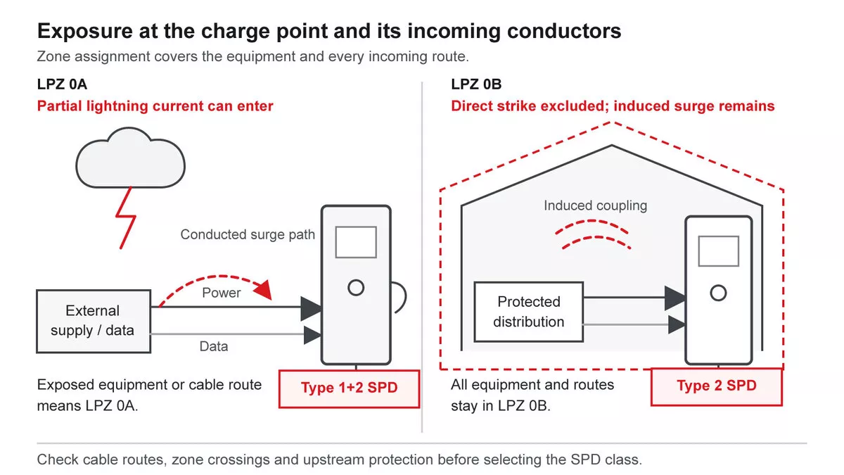
Figure 2 — Establishing the zone of the charge point and its incoming conductors, and the device class each case points to.
Specifying the AC side
Four parameters carry an EV charger surge protection specification. Uc has to sit above the highest continuous operating voltage of the system at that point, which follows from the earthing arrangement and the conductor-to-conductor voltage, not from the nominal supply voltage alone. Up has to sit below the impulse withstand voltage of the charge point electronics, with the connecting lead length accounted for. The discharge rating follows the class established above. Type 1+2 devices additionally carry a 10/350 µs lightning impulse current rating, Iimp, which is the parameter that defines the duty for a partial lightning current and varies by model, so select it against the exposure instead of against the largest figure in the family.
An EV charger surge protection device must match the supply arrangement. In TN-S and TT systems a single-phase installation takes the 1+1 arrangement and a three-phase installation takes 3+1, with the neutral-to-earth path carried by a separate component in both; IT systems take 1+0 or 3+0 instead. The SPD wiring diagram guide sets out each arrangement.
The Thor AC range covers both duties. Models for the exposed case come from the Type 1+2 range, and the protected case from the Type 2 range:
| Duty | Thor model | Class | *Uc* | *Iimp* (10/350 µs) | *In* (8/20 µs) | *Imax* (8/20 µs) | *Up* |
| LPZ 0A, 230 V | TRS5-B+C | Type 1+2 | 275 V AC | 12.5 kA | 20 kA | 50 kA | ≤1.3 kV |
| LPZ 0A, 230 V, MOV and GDT | TRS8-B+C | Type 1+2 | 275 V AC | 12.5 kA | 30 kA | 60 kA | ≤1.5 kV |
| LPZ 0B, 230 V | TRS2-C40 or TRS4-C40 | Type 2 | 275 V AC | — | 20 kA | 40 kA | ≤1.5 kV |
| LPZ 0B, 380 V three phase | TRS7-B80 | Type 2 | 385 V AC | — | 40 kA | 80 kA | ≤2.4 kV |
Uc is customisable on these ranges where the earthing arrangement or a higher system voltage calls for it, with 320 V and 385 V variants available. Match Iimp to the partial lightning current the zone assessment produces: where the assessment puts a high conducted partial lightning current at the charge point, check the figure against that result before accepting a model on the rest of its ratings.
One practical point gets missed on unattended sites: the remote signalling contact stops being a convenience. A charge point whose SPD has reached end of life looks identical from the road to one that has not, so the fault has to travel back over the monitoring link or nobody learns about it until the next failure.
Enclosure space is the other recurring constraint. Where a Type 2 duty has to be met and the charge point has no spare DIN rail capacity, a wall-mounted lightning protection box upstream meets it at 380 V AC in L-PE and N-PE modes. A Type 1 or Type 1+2 requirement needs an assembly rated for that duty, which is a different specification.
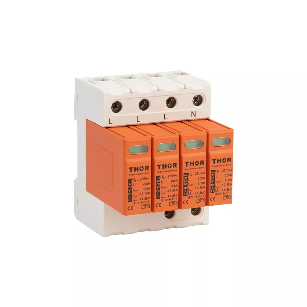
Figure 3 — Thor AC Type 1+2 surge protective device.
The DC side, and which standard applies
A DC fast charger has a second protection problem, and the first thing to get right is which product standard the device is built to. IEC 61643-31 covers SPDs for the DC side of photovoltaic installations and nothing else. The standard for SPDs on general low-voltage DC power systems is IEC 61643-41:2025, which explicitly excludes photovoltaic applications and is the relevant document for a charging DC bus.
The distinction is not administrative. A PV array is a current-limited source with a characteristic fault behaviour; a charging DC bus backed by grid-fed power electronics or storage is not, and the short-circuit and follow-current conditions the SPD has to survive differ accordingly. The project specification therefore has to separate PV, the traction-voltage charging bus and the charger’s low-voltage auxiliary circuits instead of selecting an SPD from DC voltage alone.
Beyond the standard, selection follows the AC logic. The protection level has to land below the withstand voltage of the equipment, the device has to be rated for the bus voltage with margin, and the protection modes differ: positive to earth, negative to earth, and positive to negative. A DC arc does not self-extinguish at a current zero the way an AC one does, which is why the disconnection and short-circuit ratings matter more here than on the AC side. The general method is covered in the DC surge protection device guide.
Low-voltage auxiliary and control circuits inside the charger are a separate, usable application. Thor’s TRS3 DC range covers four nominal DC voltages for those circuits, with In 20 kA and Imax 40 kA:
| Auxiliary circuit | *Uc* | *Up* |
| 24 V DC nominal | 36 V DC | ≤0.6 kV |
| 48 V DC nominal | 65 V DC | ≤0.7 kV |
| 75 V DC nominal | 80 V DC | ≤0.8 kV |
| 110 V DC nominal | 180 V DC | ≤0.9 kV |
That makes the auxiliary-circuit SPD one layer of the overall EV charger surge protection scheme, not a substitute for protection selected for the traction-voltage DC bus.
Use these variants only where the actual auxiliary circuit voltage, fault current and protection modes match the device data. They do not cover the traction-voltage fast-charging bus. EV charger surge protection on that high-voltage bus still has to be specified to IEC 61643-41 against the charger manufacturer’s stated withstand voltage and fault conditions, as a selection separate from both the auxiliary DC and the AC supply feeding the cabinet.
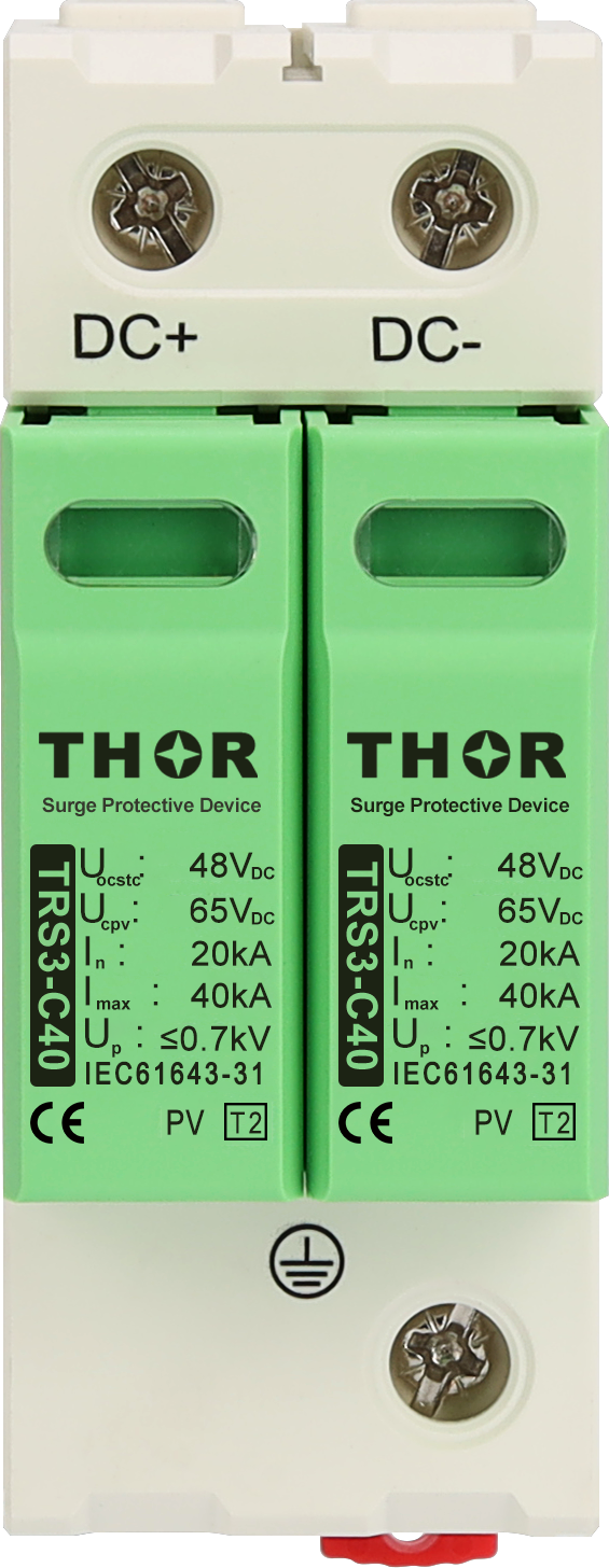
Figure 4 — Thor TRS3-C40 48 V DC SPD, shown as a representative option for a matched low-voltage auxiliary circuit.
Protecting the communication lines
Communication lines are the usual survivor of an otherwise protected site: the power side gets an SPD, the data run gets nothing, and the unit comes back with a working contactor and a dead controller. Any EV charger surge protection scheme that stops at the power terminals is incomplete. A charge point’s Ethernet or PoE backhaul and its RS485 control line each need a signal SPD to IEC 61643-21, selected for the interface voltage and the data rate it has to pass.
| Interface | Thor range | *Uc* | Discharge rating |
| Ethernet / PoE | TRSS-RJ45 | 57 V PoE | 10 kA L-PE |
| RS485 control line | TRSS-485 | 8 V to 110 V depending on variant | 10 kA Imax |
The interface-level detail is secondary to matching Uc, discharge rating and data rate to the actual port, so the product range should be selected from the interface specification rather than from the charger label alone.
A data run between a building and a charge point in a car park raises a question beyond the surge itself. Where the two ends sit on separate earth electrodes, a potential difference can appear between the references, and how the cable screen is terminated determines whether that difference drives current through the screen. Screen termination is a site-specific design decision: bonding at both ends gives the best high-frequency performance and is the normal arrangement within one bonding network, while a single-end bond with a controlled path at the far end is one option where two earth references are separate. Which applies depends on the bonding network, the cable construction, the port isolation of the equipment and the installation standard in force, so it belongs with the site design instead of in a general rule. For EV charger surge protection on copper data lines, signal SPD selection is separate from screen termination and neither substitutes for the other.
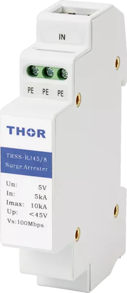 | 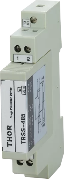 |
Figure 5 — Thor signal-line surge protective devices for Ethernet and RS485.
What the SPD discharges into
An SPD does not absorb a surge. It diverts current away from the equipment and into the earthing system, so EV charger surge protection is only as good as the path that current finds. Fit the correct device on an incomplete earthing arrangement and the voltage that appears at the protected equipment will not be the Up on the datasheet.
Figure 6 traces that current through the SPD, the local bonding bar and the earth electrode while keeping the incoming PE or PEN visible as a separate function.
Three separate requirements meet at a charge point and are worth keeping apart, because they are designed against different rules.
The first is the bonding requirement for the SPD itself. Where a Type 1 or Type 1+2 device is installed in a charge point, IEC 60364-5-54 calls for a separate equipotential bonding connection to the local earthing system, and a connection to the PEN or PE conductor arriving from the distribution network is not sufficient on its own. The device needs a local path into earth, not a borrowed one.
The second is the electrode design that carries that current away. Electrode design for EV charger surge protection is site-specific. Published examples give an order of magnitude: for a class III lightning protection system, an earth rod of around 2.5 m or a radial electrode of around 5 m below the frost line, with 10 Ω cited in IEC 62305 as a recommended value rather than a pass mark. Treat those as illustrations of scale. The electrode a site actually needs comes from its soil resistivity, its LPS class where one applies, and the risk assessment behind it, and requirements for public charging infrastructure vary by country. Germany, for instance, reaches a ring earth electrode through national rules rather than through IEC directly.
The third is the protective earthing of the EV installation itself, including the open-PEN detection and disconnection measures that apply where a charge point is supplied from a PME or TN-C-S arrangement. Those measures exist for shock protection under a broken neutral, and they are designed against the wiring regulations for the supply arrangement, not against the surge concept. Which arrangement the site starts from matters for both questions, and TN-C-S is the supply most UK charge points are connected to, but the two sets of measures should not be conflated.
Where a charging park is designed as one common earth-termination and equipotential-bonding system, the individual electrodes should be interconnected into a mesh, with the distribution cabinets and every charge point bonded into it. Separate unconnected electrodes inside that common system give each charge point its own reference, which is the condition that puts potential differences across the data runs between them.
One safety consequence sits outside the equipment question entirely. Where a charging canopy carries a lightning protection system with bare down conductors, people stand with a charging cable in hand within reach of a conductor that may carry lightning current. Step and touch voltage then has to be assessed for the positions people actually occupy, and controlled with potential grading or insulated down conductors where the assessment calls for it.
Earthing and bonding hardware is installation scope rather than a device selection, so this section points at no product. It remains the part of an EV charger surge protection scheme that most often decides whether the rest of it works.
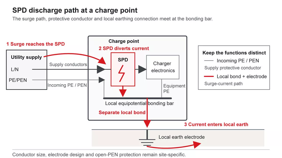
Figure 6 — The SPD discharge path: the device, its own bonding connection, and the local earth electrode.
FAQ
Do EV chargers have surge protection built in?
Some charge points include a surge protective device and many do not, and a built-in device is not automatically the class the EV charger surge protection design needs. Check three things against the unit’s documentation: which class it is tested to, its Up against the withstand voltage of what it protects, and whether it can be replaced in the field after it has operated. Where the zone assessment calls for a Type 1+2 duty and the built-in device is a Type 2, the installation still needs the upstream device.
Does a domestic wallbox need the same EV charger surge protection as a public charging post?
The decision runs in two stages and the two installations can differ at either. First, whether protection is required at all: the provisions that apply to a publicly accessible charging facility are not the same as those for a private installation, and IEC 60364-4-44 clause 443 works from the consequence of failure. Second, once protection is required, the EV charger surge protection class comes from the exposure assessment, not from who uses the charge point. A domestic post standing in the open at the end of a driveway can reach the same class requirement as a public one in a comparable position.
What happens to the SPD after it has taken a surge?
A varistor-based device ages, and each diverted surge degrades it. When degradation reaches the point where the varistor would overheat, the thermal disconnector isolates it. The device disconnects safely, and the installation no longer has surge protection from that SPD. The status indicator shows the change at the device. On an unattended charge point nobody reads a local indicator, which is why the remote signalling contact belongs in an EV charger surge protection specification rather than in the options list.
Specifying EV charger surge protection for a charging project
Getting EV charger surge protection right comes down to four inputs: where each charge point sits relative to any lightning protection system, and how the supply and data cables run to it; the system earthing arrangement; the AC supply voltage and number of phases; and which communication interfaces reach the unit. Send those to our team and we will come back with the device classes and models that match, including the signal-line protection for the data runs.