
A lightning protection zone (LPZ) is a defined area within or around a structure where the lightning electromagnetic environment is controlled to a specific level. IEC 62305-4 divides structures into nested zones — from LPZ 0A, where direct strike exposure is uncontrolled, to LPZ 2 and beyond, where sensitive electronics operate in a fully attenuated environment. The SPD type at each boundary depends on the threat crossing it: Type 1 at LPZ 0A boundaries, Type 2 at LPZ 0B and inner boundaries.
What Is a Lightning Protection Zone?
External lightning protection — air terminals, down conductors, earth electrodes — stops a direct strike from igniting a building or injuring people nearby. It does not stop the electromagnetic pulse that travels with every lightning discharge. A 30 kA strike generates a lightning electromagnetic impulse (LEMP) that induces voltage transients on every conductor within hundreds of metres: power cables, data lines, signal wiring, metallic structures.
The lightning protection zone concept, defined in IEC 62305-4, solves this by dividing a structure into nested zones. Each zone boundary acts as a filter. Cross the boundary with a conductor and you install an SPD rated for the threat level at that boundary. But SPDs alone do not complete the boundary — every metallic service entering the zone (pipes, cable trays, structural steel, signal cable shields) must connect to the same equipotential bonding bar. Bonding keeps all conductive parts at the same potential during a strike. Without it, a surge current flowing through one conductor raises its potential relative to unbonded metal nearby, and a flashover inside the zone destroys the protection the zone was meant to provide. Figure 1 shows how bonding ties all incoming services to a single reference at the zone boundary — without it, the SPD handles the surge on the power line but the unbonded data cable shield becomes the flashover path.
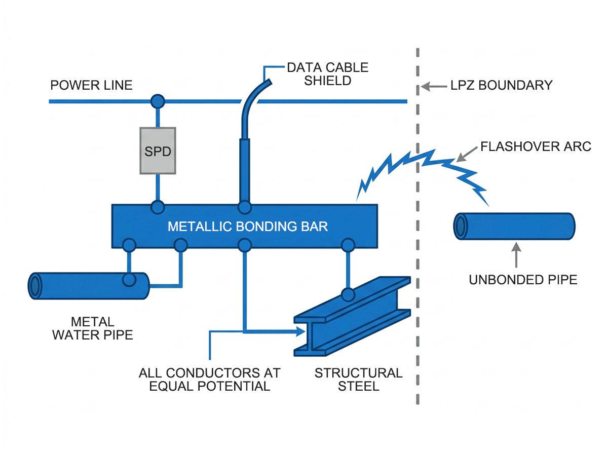
Figure 1 — Equipotential bonding at lightning protection zone boundary — all metallic services bonded to common earthing bar
By the time electrical disturbance reaches PLCs, inverters, or communication equipment in the innermost zone, it has been attenuated to a level those devices can survive.
The zones do not describe where lightning hits. They describe where electromagnetic energy flows and how much of it reaches each area of the structure. As shown in Figure 2, each zone boundary is a transition point where SPDs intercept the threat crossing from one level to the next.
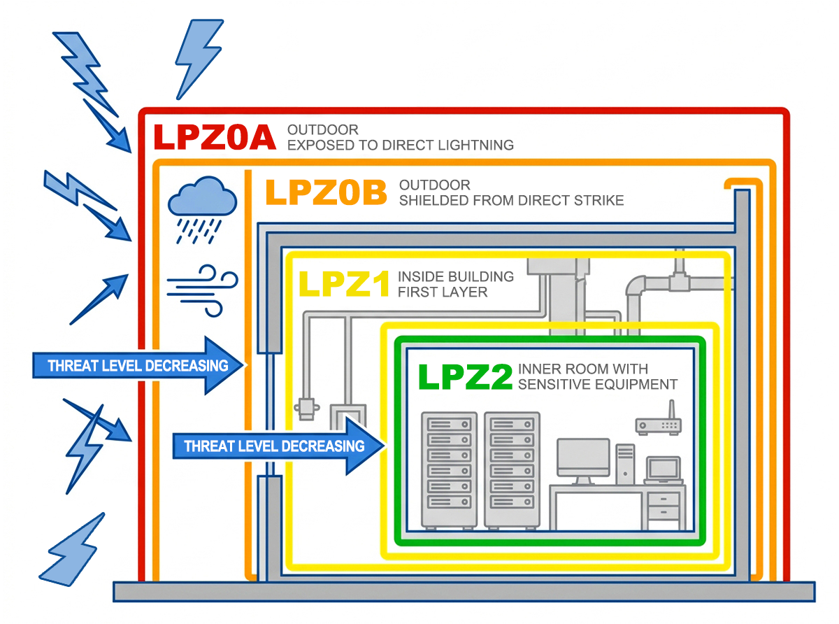
Figure 2 — Lightning protection zone concept diagram showing nested LPZ zones from LPZ0A to LPZ2 inside a building
The LPZ Classification: From LPZ 0A to LPZ 2
IEC 62305-4 defines four primary zones. Each one describes a different electromagnetic environment, and each boundary between zones is where protection decisions are made.
LPZ 0A — Direct Strike Exposure
The outermost zone. Any conductor or system here is exposed to the full lightning current and the unattenuated LEMP. Overhead power lines extending beyond the building, rooftop equipment without air terminal protection, and outdoor switchgear in unshielded areas all fall in LPZ 0A. The full 10/350 µs lightning current waveform can flow through conductors in this zone.
LPZ 0B — Shielded from Direct Strike, Not from LEMP
Still outside the building envelope, but within the protection volume of an external lightning protection system — typically within the rolling sphere radius of the air termination network. A rooftop siren, an outdoor alarm light within the protection angle of a lightning rod, or equipment inside a shielded enclosure on the roof can sit in LPZ 0B. Direct strike current is blocked, but the full lightning electromagnetic field remains present. Partial lightning currents can still appear on conductors here.
LPZ 1 — Inside the Building Envelope
The first interior zone. Surge current is limited at the building entry point by current sharing through the earthing system and by SPDs at the LPZ 0/1 boundary. The LEMP is attenuated by the building structure itself — reinforced concrete and metallic building elements contribute significantly to shielding. Distribution boards, cable routes inside the building, and general electrical infrastructure sit in LPZ 1.
LPZ 2 and Beyond — Sensitive Equipment Zones
Inner zones defined by additional shielding: a metal cabinet, a screened room, or a separately shielded enclosure within LPZ 1. Surge current is further reduced at each LPZ 1/2 boundary by additional SPDs. PLCs, SCADA servers, communication equipment, and precision instrumentation belong in LPZ 2 or higher.
| Zone | Threat | Typical Locations | Lightning Current Exposure |
| LPZ 0A | Direct strike + full LEMP | Overhead lines, unshielded rooftop equipment | Full 10/350 µs current |
| LPZ 0B | Full LEMP, no direct strike | Equipment within LPS protection volume | Partial lightning current |
| LPZ 1 | Attenuated LEMP, limited surge current | Distribution boards, cable routes inside building | Residual induced surges |
| LPZ 2+ | Heavily attenuated | Control cabinets, server rooms, PLC enclosures | Minimal residual surges |
SPD Selection at Each Zone Boundary
The SPD type at each boundary must match the threat crossing that boundary. Installing a Type 2 device where a Type 1 is needed leaves the full 10/350 µs lightning current flowing into the building unimpeded. Installing only a Type 1 at every boundary adds unnecessary impedance downstream.
LPZ 0A → LPZ 1: Type 1 Required
At this boundary, partial lightning currents in the 10/350 µs waveform can reach the SPD. Only a Type 1 lightning current arrester rated for Iimp can absorb this without being destroyed. A Type 2 device — rated for 8/20 µs — will fail under 10/350 µs stress.
The TRS-A25 delivers Iimp 25 kA (10/350 µs) with a response time under 100 ns, certified to IEC 61643-11 Type 1. It covers the LPZ 0A → LPZ 1 boundary in single-phase and three-phase service entrances.
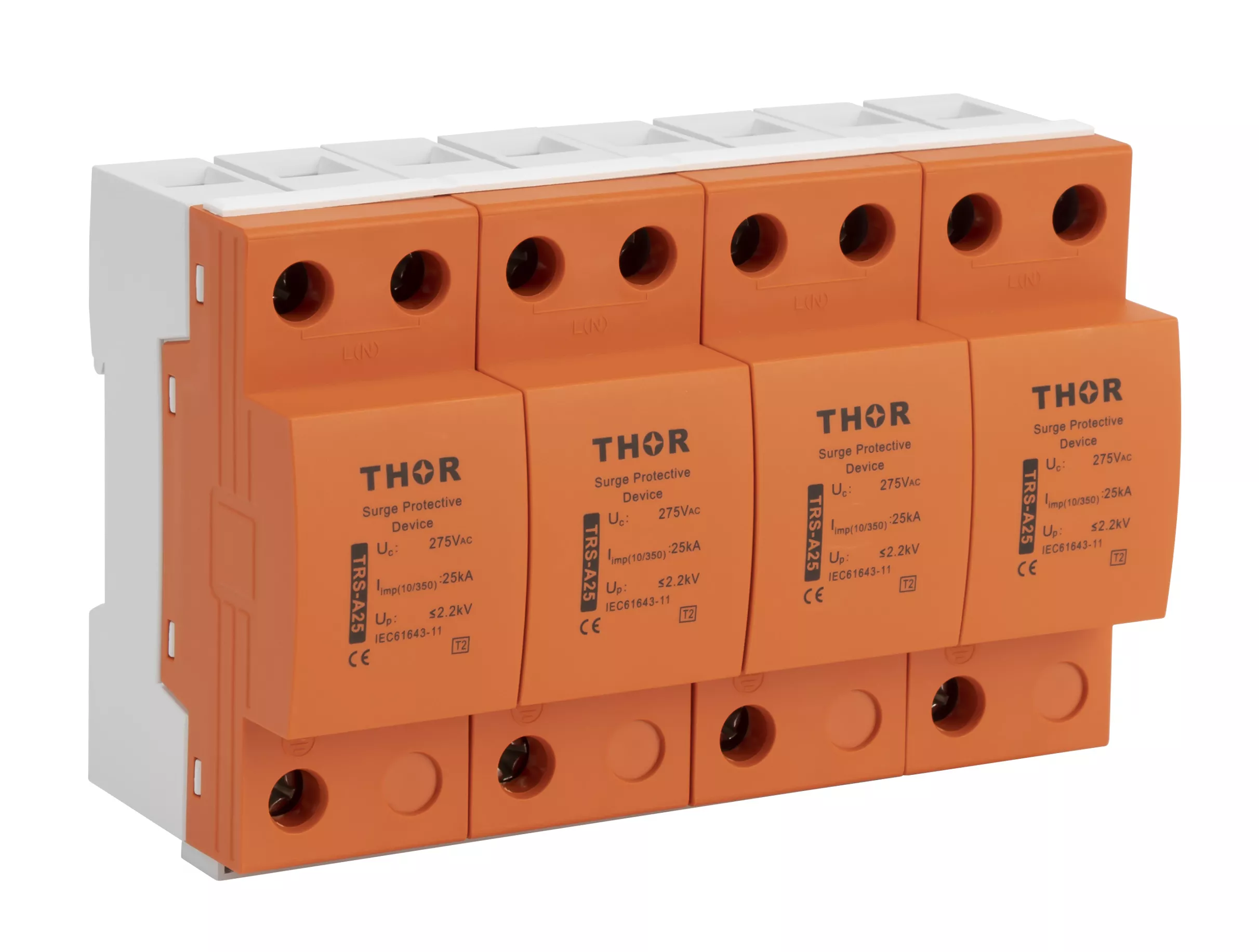
Figure 3 — Thor TRS-A25 Type 1 SPD for LPZ 0A to LPZ 1 boundary lightning protection zone
LPZ 0B → LPZ 1: Type 2 Sufficient, Type 1+2 Conservative Choice
No direct lightning current reaches this boundary — the external LPS has already intercepted the strike. The residual threat is induced surges and partial currents from the LEMP. A Type 2 device rated for the 8/20 µs waveform is sufficient under IEC 62305-4. Where the designer wants a single coordinated device or where actual current exposure is uncertain, a Type 1+2 combined arrester is acceptable and sometimes preferred.
The TRS4-C40 (In 20 kA, Imax 40 kA, Uc 275 V) covers the LPZ 0B → LPZ 1 boundary in most commercial and industrial panels. For a breakdown of how Type 1, Type 2 and Type 3 devices differ in construction and application, see our guide on Type 1 vs Type 2 vs Type 3 SPD.
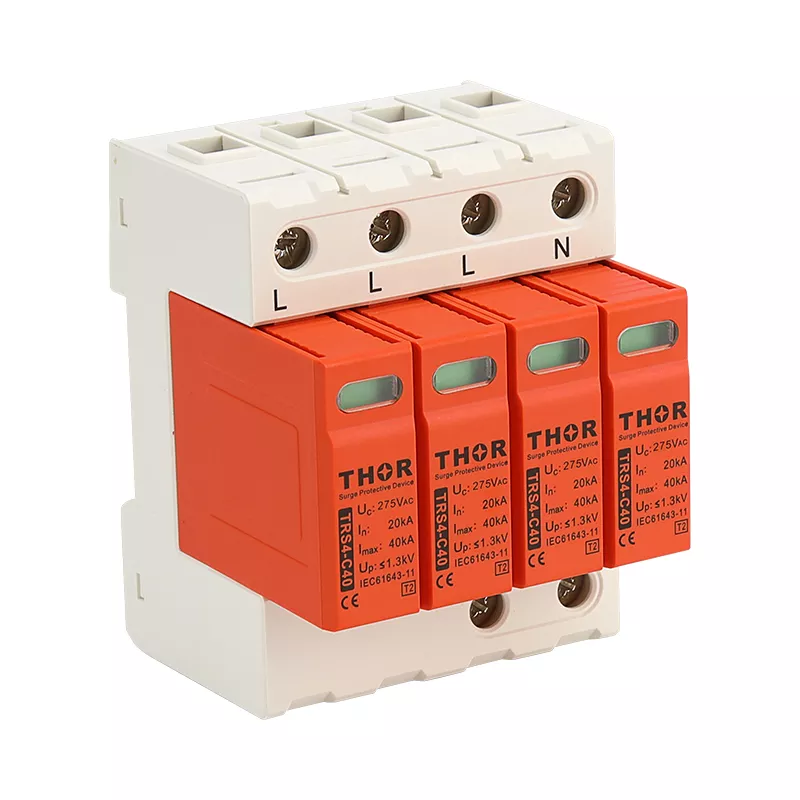
Figure 4 — Thor TRS4-C40 Type 2 SPD for LPZ 0B to LPZ 1 boundary surge protection
LPZ 1 → LPZ 2: Type 2, Low Up
At inner zone boundaries, the remaining threat is residual surge energy — induced transients from internal switching and attenuated LEMP. A Type 2 device with a low voltage protection level (Up) limits residual voltage to a level sensitive electronics can tolerate. Where equipment immunity is particularly low, a Type 3 SPD at the device terminal provides a final protection stage. Figure 5 maps the SPD type to each zone boundary — the waveform threat at the boundary determines the device rating.
| Boundary | Waveform Threat | SPD Type | Thor Example |
| LPZ 0A → LPZ 1 | 10/350 µs partial lightning current | Type 1 | TRS-A25 |
| LPZ 0B → LPZ 1 | 8/20 µs induced surge | Type 2 (Type 1+2 optional) | TRS-C40 |
| LPZ 1 → LPZ 2 | Residual surge, low energy | Type 2 low Up | TRS-D20 |
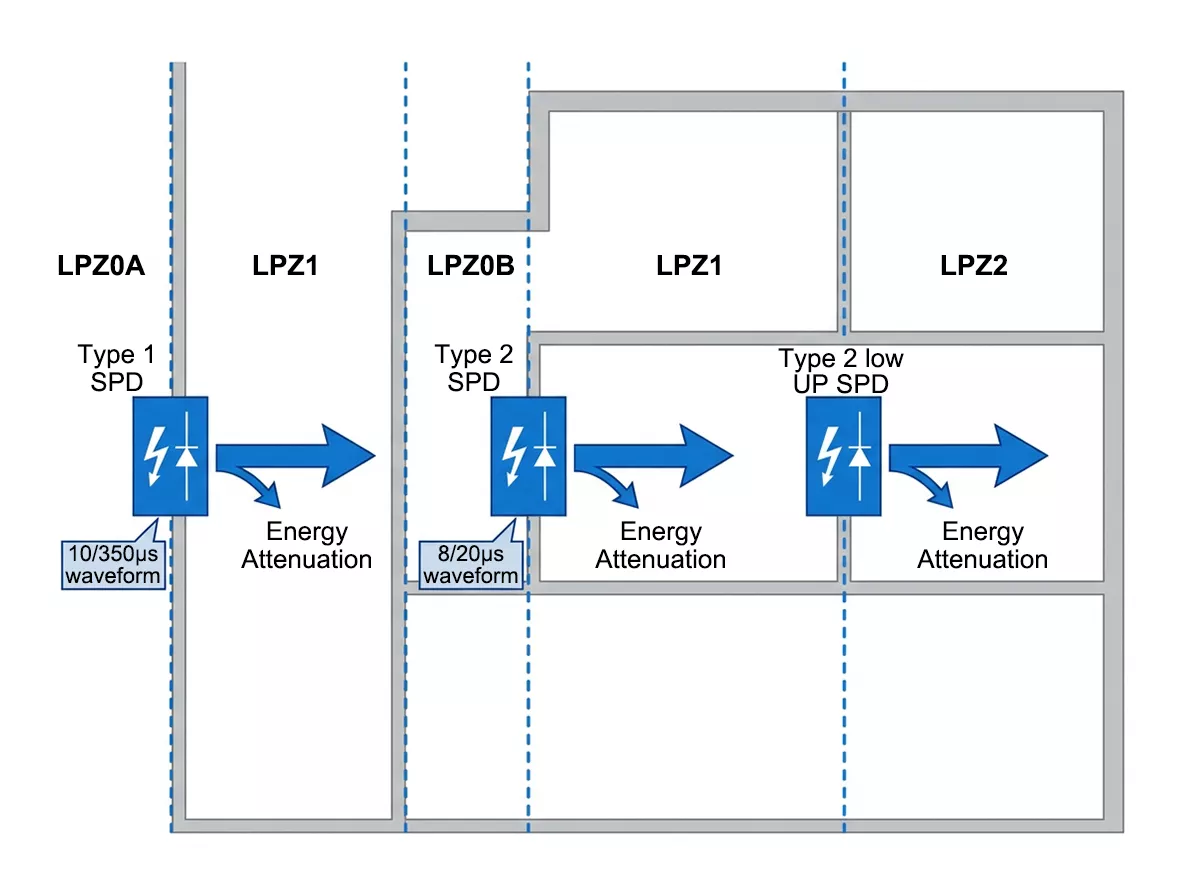
Figure 5 — LPZ boundary SPD selection diagram showing Type 1 at LPZ0A, Type 2 at LPZ0B and LPZ1 boundaries
LPZ in Practice: Industrial Facility Example
Zone classification reads cleanly on paper. Applied to a real installation, the boundaries require judgment — the same building can contain multiple LPZ levels simultaneously, and the zone a piece of equipment sits in determines which SPD protects it. In site surveys, the most common classification mistake is assigning LPZ 0B to rooftop equipment that sits outside the air termination protection angle — a device assumed shielded but actually exposed to direct strike.
A manufacturing plant with an external lightning protection system illustrates the nested lightning protection zone structure clearly.
Roof-mounted equipment outside the air termination network sits in LPZ 0A — exposed to direct strike and full LEMP. Overhead supply cables entering the site from the utility grid are also LPZ 0A until they reach the main service entrance.
Equipment on the roof within the protection volume of the air termination network — antenna masts, outdoor sensors, alarm sirens — sits in LPZ 0B. Direct strike is blocked, but the full electromagnetic field remains.
The main distribution board inside the building marks the LPZ 0/1 boundary. A Type 1 SPD at the service entrance clamps partial lightning current arriving from LPZ 0A conductors. Inside the building, cable routes, sub-distribution boards, and motor control centres operate in LPZ 1.
The production control room — typically housed in a metal enclosure or reinforced room with its own cable shielding — forms LPZ 2. PLC cabinets, SCADA workstations, and communication servers inside need a Type 2 low-Up SPD at the LPZ 1→2 boundary to keep residual surges below equipment immunity thresholds. Figure 6 maps this facility layout across all four LPZ levels and the SPD positions at each transition.
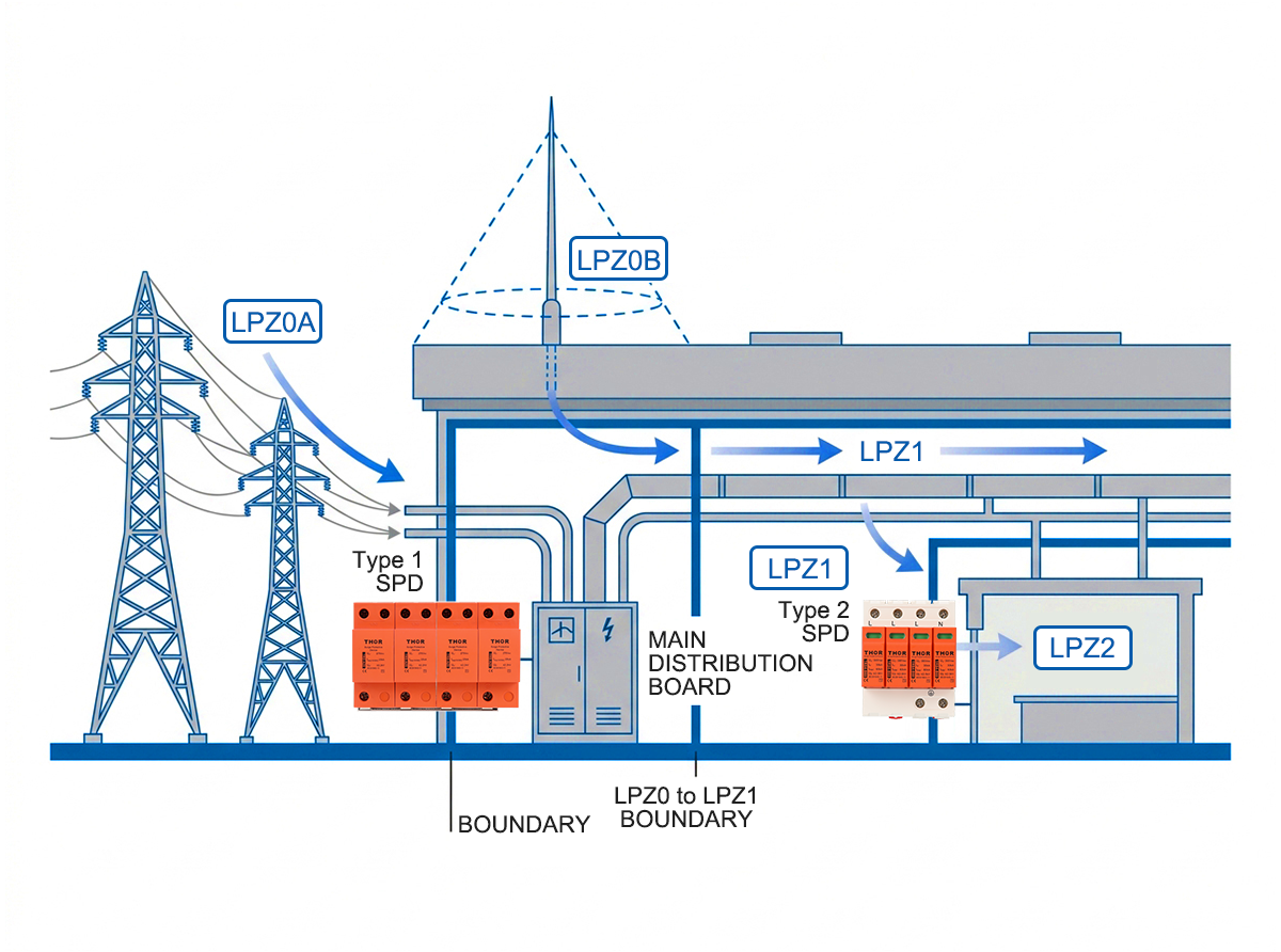
Figure 6 — Industrial facility lightning protection zone diagram showing LPZ0A rooftop, LPZ0B protected outdoor area, LPZ1 distribution board, LPZ2 control room
Coordinated SPD Protection Across Zone Boundaries
A single SPD at the building entry point is not enough. Each lightning protection zone boundary needs its own protection stage, and those stages must work together — the energy absorbed at the outer boundary determines how much residual energy reaches the next.
Protection is applied in layers, with each layer reducing the threat to a level the next layer can manage. A Type 1 at the LPZ 0A→1 boundary clamps the partial lightning current and passes a residual surge downstream. The Type 2 at the LPZ 1→2 boundary then clamps that residual surge to a voltage the connected equipment can tolerate.
Skip the outer stage and the inner stage takes the full hit — a Type 2 device rated for 8/20 µs will not survive a 10/350 µs lightning current impulse. Skip the inner stage and the residual voltage after the Type 1 — typically 1.5–2.5 kV Up — still exceeds the immunity threshold of most PLCs and communication equipment, which typically tolerate 1.5 kV or less. In panels inspected after storm damage, the most frequent gap is a missing inner-stage SPD: the Type 1 at the service entrance sat intact, but the PLC downstream absorbed the undamped residual surge.
Energy coordination between stages also requires attention to the cable length between them. IEC 61643-11 recommends at least 10 m of cable between a Type 1 and Type 2 SPD to allow sufficient inductance for the Type 1 to clamp before the Type 2 is stressed. Where the installation geometry makes 10 m impractical, a combined Type 1+2 device eliminates the coordination distance requirement by integrating both stages in a single unit. The TRS5 (Iimp 12.5 kA, Imax 50 kA) covers this application, handling both lightning current and surge duties at a single installation point.
For installation layouts showing SPD positions across zone boundaries, see our SPD wiring diagram guide.
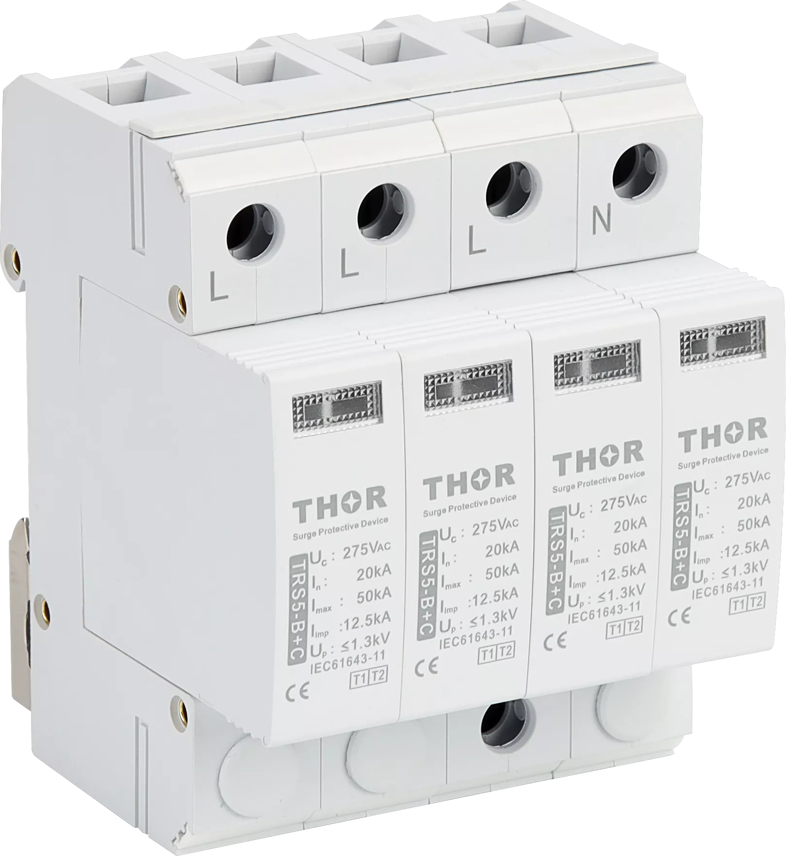
Figure 7 — Thor TRS5 Type 1+2 combined SPD for coordinated lightning protection zone boundary protection
FAQ
What is a lightning protection zone (LPZ)?
A lightning protection zone is a defined area within or around a structure where the lightning electromagnetic environment is controlled to a specific level. The concept comes from IEC 62305-4 and divides structures into nested zones — from LPZ 0A (direct strike exposure) to LPZ 2 and beyond (heavily attenuated inner zones) — so that SPDs at each boundary reduce the electromagnetic threat progressively before it reaches sensitive equipment.
What is the difference between LPZ 0A and LPZ 0B?
LPZ 0A is exposed to direct lightning strikes and the full LEMP — conductors here can carry the full 10/350 µs lightning current. LPZ 0B is protected against direct strikes by an external lightning protection system, but still exposed to the full electromagnetic field. Conductors in LPZ 0B carry partial lightning currents from induction, not direct conduction. The distinction determines whether a Type 1 or Type 2 SPD is needed at the transition to LPZ 1.
Which SPD type is needed at each LPZ boundary?
At the LPZ 0A to LPZ 1 boundary, a Type 1 SPD rated for the 10/350 µs waveform is required. At the LPZ 0B to LPZ 1 boundary, a Type 2 SPD is sufficient under IEC 62305-4, though a combined Type 1+2 is acceptable where current exposure is uncertain. At LPZ 1 to LPZ 2 boundaries, a Type 2 device with low Up protects sensitive electronics from residual surges.
What is IEC 62305-4?
IEC 62305-4 is the international standard covering protection of electrical and electronic systems within structures against lightning. It defines the lightning protection zone concept, specifies SPD requirements at each zone boundary, and provides the design framework for coordinated multi-stage surge protection. It is part of the broader IEC 62305 series on lightning protection.
Thor Electric Surge Protective Devices
Thor Electric manufactures IEC 61643-11 and TUV-certified AC surge protective devices covering Type 1, Type 2, and combined Type 1+2 configurations for every LPZ boundary. The TRS-A series covers LPZ 0A→1 lightning current duties; the TRS-B/C/D series covers LPZ 0B→1 and LPZ 1→2 surge protection; the TRS5 combined arrester eliminates coordination distance requirements where panel geometry limits cable routing. Pluggable modular design allows field replacement without rewiring. Samples, custom Uc ratings and OEM configurations are available on request.
Need free testing samples, custom Uc ratings, or OEM configurations? Contact our engineering team today to discuss your project specifications or request a quick quotation.