
To decide what size MCB for SPD protection to use, start with the SPD manufacturer’s coordination table: select the listed breaker series, current rating and trip curve, then check its breaking capacity against the installation’s prospective short-circuit current. A 32 A or 63 A breaker is a result of that selection. The SPD’s surge rating, such as 40 kA, cannot be converted into an MCB amp rating.
First check whether an extra breaker is needed at all. Suitable upstream protection or an SPD with appropriate internal protection can remove the need for a separate branch MCB.
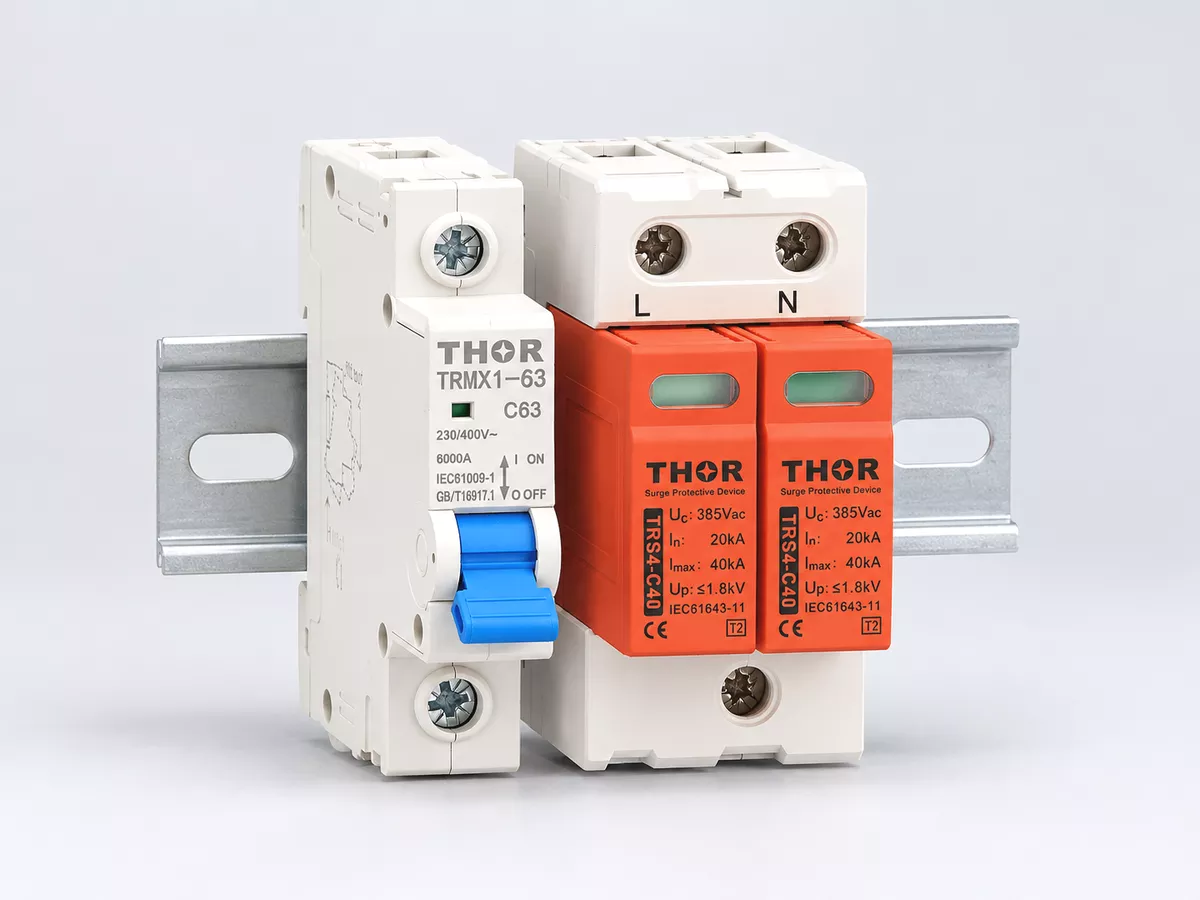
Figure 1 — An illustrative MCB and SPD pairing on a DIN rail
What size MCB for SPD protection should you choose?
Choose an MCB that meets both the SPD’s coordination requirements and the circuit’s fault conditions. For an AC DIN-rail SPD, use this sequence:
- Find the SPD’s backup-protection table or installation sheet. Identify the permitted MCB series, current rating and trip curve.
- Compare the existing upstream protective device with the permitted arrangement. A suitable upstream device may already cover the SPD branch.
- If a separate MCB is required, choose a listed combination. Keep the breaker within the specified limits and check any minimum rating for surge withstand.
- Check the breaking capacity, branch-conductor protection and terminal requirements at the installation point.
The useful answer to “what size MCB for SPD protection?” is therefore a complete specification, such as an approved C32 breaker with the required voltage, pole arrangement and breaking capacity. “32 A” alone leaves too much undecided.
Does the SPD need its own MCB?
Not every SPD needs a separate MCB. The installation needs a suitable short-circuit protection arrangement, which can take three forms:
| Arrangement | When it fits | What to check |
| Existing upstream protection | The upstream fuse or breaker is included in the permitted SPD arrangement | Device type and rating, combination short-circuit rating, branch conductors |
| Separate SPD-branch MCB or fuse | The upstream device exceeds the SPD’s limits, or a separate protected branch is chosen | Approved backup device and coordination with upstream protection |
| Suitable internal protection | The SPD instructions permit installation without an extra branch protective device | Stated fault-current limits and any required upstream protection |
Figure 2 shows where the backup protection sits in each arrangement.
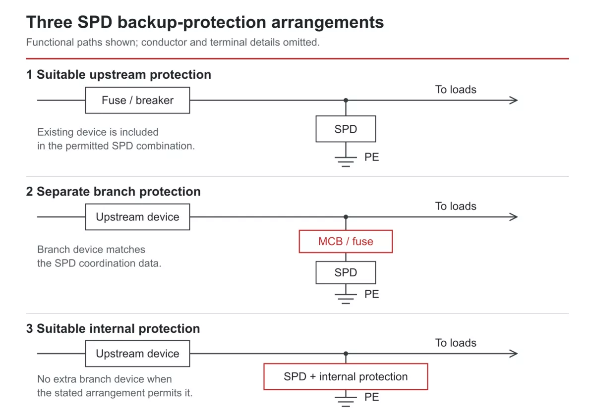
Figure 2 — Upstream, separate-branch and internal SPD protection arrangements.
An internal thermal disconnector responds to overheating as the SPD degrades. Its presence alone does not establish that the SPD can safely clear a short circuit. The installation sheet must identify the permitted protection arrangement.
The IET’s explanation of SPD overcurrent protection confirms that protection can be internal or external. It also explains when a UK distributor’s cut-out fuse may be used under the BEAMA/ENA conditions. That is a defined consumer-unit arrangement, not blanket permission to rely on any incoming fuse.
A separate branch breaker can make SPD maintenance more convenient. Keeping the rest of the board energised during an SPD fault also requires selectivity between the branch and upstream devices; merely adding a smaller breaker does not establish that selectivity.
For the physical branch arrangement, see the SPD wiring diagrams. Settle the protection arrangement before ordering the breaker.
Read the ratings that decide the selection
When checking what size MCB for SPD protection a datasheet permits, the difficult part is often finding the complete pairing information. A line labelled “maximum backup fuse” answers only part of the question.
| Data to find | Where to look | How it affects your choice |
| Permitted MCB series, curve and current | Coordination table or installation instructions | Defines the breaker combination to select |
| Maximum backup fuse and fuse class | SPD datasheet and detailed instructions | Sets the stated fuse limit; retain the fuse class, such as gG |
| SPD short-circuit rating with backup protection | Combination data, sometimes labelled SCCR or Isccr | Must cover the fault current available at the SPD installation point |
| MCB breaking capacity at the operating voltage | Breaker data and panel-design information | Establishes whether the breaker can interrupt the available fault current |
| Conductor sizes and terminal limits | SPD instructions and circuit design | Defines suitable connections and conductor protection |
A 125 A gG maximum backup-fuse entry does not authorise a 125 A MCB. Fuses and breakers have different operating characteristics and energy let-through. Obtain the breaker pairing if an MCB is the intended choice.
The same applies to substitutions between breaker brands or series. “C curve, 32 A” describes two characteristics; coordination data may specify a particular series as well.
For a standalone breaker selection, its applicable breaking capacity must meet or exceed the prospective short-circuit current. A lower-rated breaker can be used in a documented, tested backup combination with an upstream device, but that requires the combination’s rating. Do not assume an upstream fuse automatically raises every downstream breaker’s capacity.
Keep these fault ratings separate from the SPD’s discharge-current ratings. The guide to reading SPD ratings explains In and Imax. Neither value tells you what size MCB for SPD protection to buy.
Work through three MCB selection examples
These are assumed teaching configurations, with the permitted combinations stated explicitly. They show how to decide what size MCB for SPD protection fits a set of inputs.
Example 1: C32 is specified and the fault current is 4 kA
Suppose a Type 2 SPD’s coordination table lists a particular C32 MCB series, including its 6 kA version at the circuit voltage. The prospective short-circuit current at the board is 4 kA. The branch conductors meet the SPD’s connection requirements and the circuit’s protection requirements.
Select the listed C32, 6 kA breaker. Its 32 A current rating matches the pairing, and its 6 kA breaking capacity exceeds the 4 kA fault level.
A spare B6 breaker is not an equivalent replacement. Both the current rating and trip curve have changed, and the stated combination no longer applies. A lightly loaded SPD branch is insufficient reason to make that substitution.
Record the breaker catalogue number on the panel schedule. That prevents a later purchase order from reducing the specification to “32 A MCB” and losing the approved series or breaking capacity.
Example 2: An existing 100 A gG fuse already fits
Suppose the SPD documentation permits upstream gG fuses through 125 A, explicitly including 100 A. A customer-owned distribution-board fuse is 100 A gG. The documented combination covers the available fault current, and the SPD branch conductors are suitably protected.
No extra MCB is required solely to add backup protection for this SPD. The existing fuse fulfils that role. Asking what size MCB for SPD protection to add would skip the more useful finding: the required protection already exists.
Now change the upstream fuse to 160 A. It exceeds the SPD’s stated 125 A limit. Add a permitted SPD-branch protective device or select a different SPD arrangement. Leaving the branch unchanged would lose the documented protection configuration.
The example uses a customer-owned board fuse; applying the same idea to a UK distributor’s sealed cut-out requires the specific conditions discussed above.
Example 3: The fault current rises to 8 kA
Return to the C32 arrangement, but place it at a board with 8 kA prospective short-circuit current. Assume the SPD table also lists the series’ 10 kA C32 version, with the SPD combination rated for this fault level.
Choose that C32, 10 kA version. Without a documented upstream backup combination, the 6 kA breaker is insufficient here.
The change is 6 kA to 10 kA breaking capacity; the rated current remains 32 A. Moving to 63 A would change a different parameter and require its own coordination check.
Figure 3 separates the unchanged current rating from the higher breaking capacity.

Figure 3 — C32 selections at 4 kA and 8 kA prospective fault levels in the assumed examples.
Together, these examples separate two decisions that often get merged: what size MCB for SPD protection the pairing permits, and what fault-interrupting capacity the location requires.
Why a smaller MCB can disconnect surge protection
A parallel-connected SPD carries very little current during normal operation. During a surge, its branch conducts a brief, much larger pulse. If the SPD fails short circuit, the branch can then carry power-frequency fault current until protection disconnects it.
Those three conditions explain why selecting a breaker from the SPD’s normal operating current gives the wrong answer. The backup device must survive the specified surge duties while disconnecting the relevant fault.
Replacing a coordinated 32 A MCB with a 6 A device can reduce the combination’s surge withstand or cause unwanted disconnection. Once the SPD branch opens, the loads may keep running without the intended surge protection. Smaller amperage is therefore no shortcut to a better selection.
The B or C trip curve alone cannot settle the question either. The usual magnetic-trip ranges describe breaker behaviour under specified power-frequency test conditions. Comparing those multiples directly with the peak of a microsecond surge does not predict whether the breaker will trip or withstand that impulse.
Use the tested combination to answer what size MCB for SPD protection will preserve the intended surge performance. If a replacement is needed, check the full series and rating before changing the branch.
When to use a fuse or an SCB instead
An MCB is convenient where reset and switching access matter. Other backup devices may suit the available coordination data or the panel layout better.
| Backup device | Reason to choose it | Selection detail |
| MCB | Resettable device and accessible branch switching | Match the listed series, curve, current and fault rating |
| gG fuse | A documented fuse pairing fits the installation | Match the fuse class and rating; allow access for replacement |
| Surge backup protective device, often called SCB | A purpose-built SPD backup combination is documented | Check the exact SPD pairing, surge duty and short-circuit rating |
An SCB label alone says too little to justify a substitution. Compare the combination data and maintenance needs before changing device type. Where the SPD sheet lists only fuse protection, request the MCB pairing instead of treating the fuse amperage as an MCB recommendation.
FAQ
What size MCB for SPD protection is needed with Type 1?
Use the backup-protection data for that Type 1 SPD. IEC Type 1 selection includes the 10/350 μs impulse duty, so a Type 2 pairing cannot simply be carried over. A Type 1 SPD may use a fuse, breaker or suitable internal arrangement. The Type 1, Type 2 and Type 3 comparison explains the different test duties.
Does a 40 kA SPD need a 40 kA circuit breaker?
No. A Type 2 SPD’s 40 kA Imax describes its maximum discharge current under an 8/20 μs impulse test. A breaker’s kA breaking-capacity rating concerns interruption of short-circuit current. The SPD coordination data determines the backup device; the installation’s fault level determines the required fault-interrupting capacity.
Specify the SPD and backup protection together
Choosing what size MCB for SPD protection belongs in the same purchase decision as the SPD. For a Thor AC surge protection device, send the selection details: the SPD model, system voltage and phases, upstream protective-device type and rating, and available fault current. Ask for the corresponding backup-protection requirements with the SPD specification.