RS485 differential signaling resists electrical noise well. A lightning-induced surge that shifts ground potential by several thousand volts is a different problem entirely — one that kills the port. The common-mode voltage overwhelms the transceiver’s input range, and the failure is silent until someone checks. RS485 surge protection stops that failure path before it reaches your equipment..
Why RS485 Networks Are Still Vulnerable to Surges
RS485 uses differential signaling — the receiver reads the voltage difference between the A and B lines, not an absolute voltage. Noise that hits both conductors equally gets cancelled out. Surges don’t work that way.
The vulnerability comes from ground potential rise (GPR). When a lightning strike or high-energy fault hits a site, two physically separate grounding points can sit at very different potentials. The ground at a remote field device rises sharply relative to the control room, and that difference drives a large common-mode voltage into the cable. RS485 transceivers tolerate a common-mode range of −7 V to +12 V. A nearby strike can push that difference into the thousands of volts — well past what the input can survive.
RS485 surge protection limits this common-mode voltage before it reaches the transceiver. A compliant SPD — tested to IEC 61643-21 for signaling line applications — diverts the surge current to the local protective earth and clamps the residual voltage to a level the transceiver can survive. Without it, long RS485 runs crossing buildings, outdoor cable trays, or separate grounding domains are failure events waiting for the next thunderstorm.
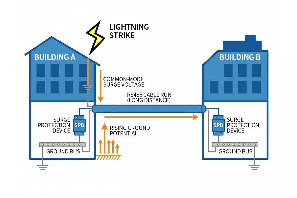
Figure 1 — Ground potential rise drives common-mode voltage into RS485 cables during lightning events, exceeding the transceiver’s input range
Where to Install RS485 Surge Protection
Placement determines whether the SPD actually intercepts the surge before it damages the transceiver. Getting the location wrong — even with the right device — leaves your equipment exposed.
Near end protection
Install the SPD at the control room or panel side, as close as possible to the cable entry point of the enclosure. The SPD sits in series with the RS485 signal lines, between the cable entry and the transceiver or PLC input. Keep the connection leads short. Every extra centimetre of lead adds inductance, which reduces the SPD’s effectiveness during fast transients.
Far end protection
The remote field device — a sensor, RTU, motor drive, or flow meter — needs its own SPD if it sits in a different building, on a separate structure, or in a different grounding domain. A single SPD at the control room end does not protect the far-end transceiver from a surge arriving from outside. The surge enters the cable from the exposed side, travels along the line, and reaches the unprotected port before any clamping occurs.
As shown in Figure 2, dual-end protection creates two interception points, preventing surge current from flowing through the transceiver path at either end.
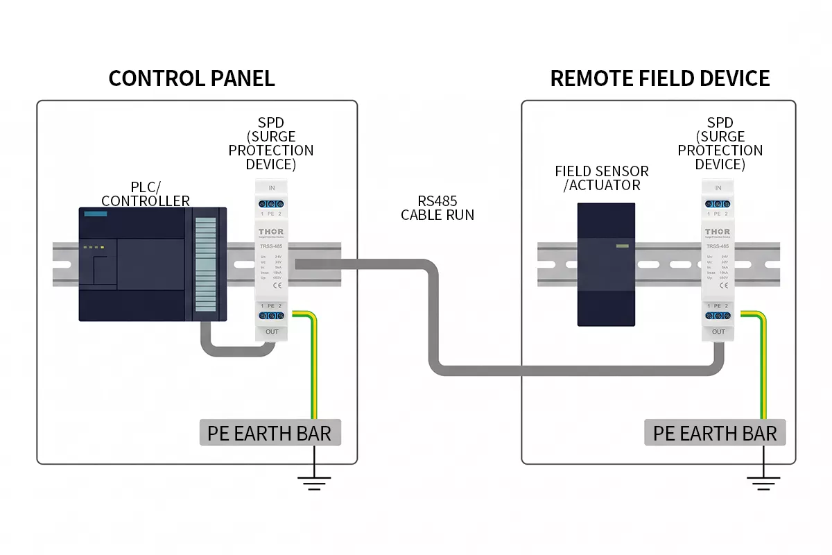
Figure 2 — RS485 SPD installation at near end (control panel) and far end (remote field device), with both units bonded to local PE
When dual-end protection is required
Install SPDs at both ends when any of the following apply:
- Cable crosses between two buildings or structures
- Any portion of the cable run is outdoors or on an exposed cable tray
- The two ends sit on separate earthing systems
- Cable length exceeds 100 m in a lightning-prone industrial environment
When the entire run stays inside one well-bonded facility with a controlled environment, protecting the panel entry point is the minimum. Dual-end protection remains the safer design.
Installation rules
- Mount the SPD as close to the cable gland or entry point as physically possible
- Connect the SPD earth terminal directly to the local equipotential bonding bar or PE busbar
- Do not route the SPD earth lead alongside the RS485 signal cables — keep it separate and as short as possible
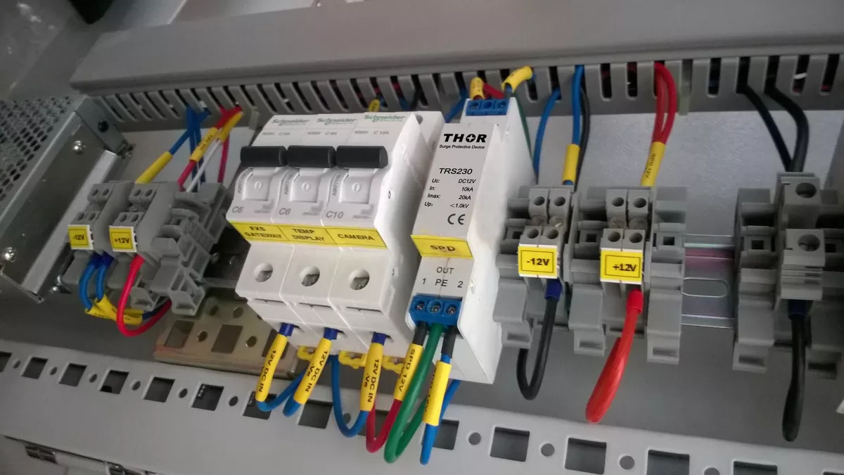
Figure 3 — Thor SPD mounted on DIN rail alongside MCBs in an industrial control cabinet, with labeled DC signal lines
How to Select an RS485 Surge Protector
Not every signal line SPD works on RS485. The device needs to pass data at the speeds your system runs while surviving the surges your site generates. Four parameters drive the selection.
A Modbus RTU link running at 24 V across two factory buildings has different requirements from a 5 V sensor bus inside one panel. Start with the system voltage, then work through the remaining parameters.
Continuous operating voltage (Uc)
Uc must sit above the RS485 signal voltage under normal operating conditions. Selecting a device with Uc too close to the signal voltage causes the SPD to conduct partially during normal operation, degrading the signal and shortening the device’s service life.
Match Uc to your system voltage:
| System voltage | Recommended Uc | Typical application |
| 5V | 8V | Short-range RS485, sensor buses |
| 12V | 15V | Building automation, BACnet |
| 24V | 30V | PLC I/O, Modbus RTU, industrial control |
| 100V | 110V | Long-distance RS485, legacy SCADA |
Discharge current (In and Imax)
In is the peak current the SPD can withstand repeatedly without degradation. Imax is the single-event maximum. For industrial sites with outdoor cable runs or frequent storm activity, select a device with In ≥ 5 kA. A higher In rating means longer service life under repeated surge events, not just survival of one large hit.
Data rate and insertion loss
RS485 supports data rates up to 10 Mbps. The SPD’s cutoff frequency must exceed your system’s highest operating frequency, with insertion loss below 1 dB across that range. At higher insertion loss, signal integrity degrades at speed — the SPD itself becomes a communication problem.
Compliance standard
RS485 signal line SPDs fall under IEC 61643-21, not IEC 61643-11. The latter covers AC power line protection. Specifying an IEC 61643-11 device on a signal line gives you a product tested against the wrong waveforms and failure modes. Confirm IEC 61643-21 compliance before purchasing.The protection components inside a compliant RS485 SPD — typically a gas discharge tube (GDT) combined with TVS elements — are selected specifically for data line waveforms.
Wiring format
RS485 runs as either 2-wire half-duplex (one twisted pair, A and B) or 4-wire full-duplex (two pairs). Confirm the SPD matches your topology — a 2-wire device on a 4-wire bus leaves two conductors unprotected.
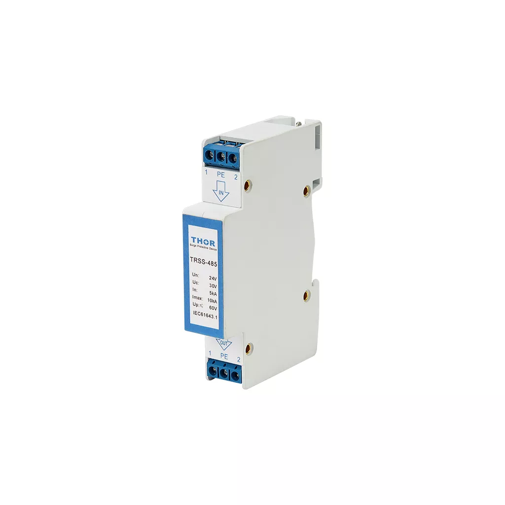
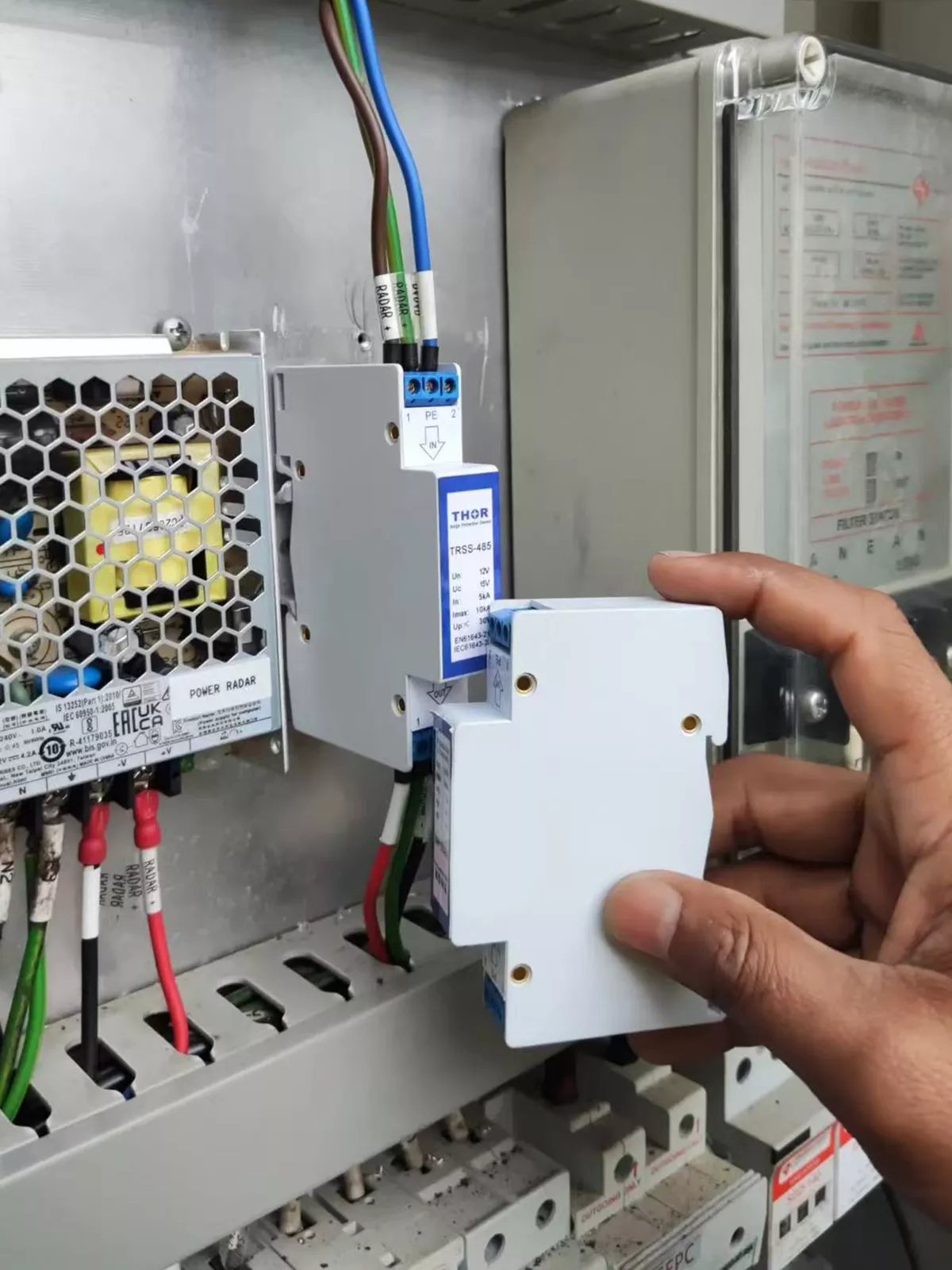
Figure 4 — Thor TRSS-485 18mm RS485 surge protection device (left) and pluggable module replacement in the field (right)
The Thor TRSS-485 covers all four voltage ratings shown in the table above, with In 5 kA, Imax 10 kA, cutoff frequency 30 MHz, and insertion loss ≤ 0.5 dB. It mounts on a standard 35 mm DIN rail and is certified to EN/IEC 61643-21. As shown in Figure 5, the device wires in series with the RS485 signal pair, with the PE terminal connected directly to the enclosure bonding bar.
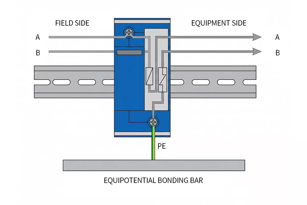
Figure 5 — TRSS-485 wiring diagram showing series connection on RS485 signal lines with PE earth bonding
For network-based industrial systems running Ethernet alongside RS485, see our guide to Ethernet surge protection.
Grounding Requirements for RS485 Surge Protection
Miss the grounding and the SPD has nowhere to send the surge — the transceiver takes it instead. Grounding is not secondary to device selection. It determines whether the SPD works at all.
Bond to the local PE busbar
Connect the SPD earth terminal directly to the equipotential bonding bar or PE busbar inside the enclosure. Do not run the earth lead to a remote grounding point. Every metre of lead adds inductance, and inductance slows the surge diversion path. During a fast transient, a long earth lead means the SPD clamps late — the residual voltage reaching the transceiver is higher than the SPD’s rated Up.
Target 0.5 m or less for the earth lead. Shorter is always better.
Separate the earth lead from signal cables
The SPD earth lead carries surge current during a transient event. Running it parallel to the RS485 signal pair creates inductive coupling — the surge current in the earth lead induces voltage onto the signal conductors, partially defeating the protection. Route the earth lead separately, and where the two must cross, cross at 90 degrees rather than running parallel.
Shield grounding: single point, control room side
RS485 cables are typically shielded twisted pair. Ground the shield at one end only — normally the control room or panel side. Grounding at both ends creates a ground loop. If the two ends sit at different potentials during a fault, current flows through the shield, adding to the common-mode stress on the signal pair.
The SPD ground and the shield ground serve different functions. The SPD earth terminal connects to PE for surge diversion. The shield drain wire connects to PE at one end for EMI rejection. Both connect to the same PE busbar inside the control panel, but through separate, short leads.
Multi-point vs single-point earthing
Multi-point earthing works only when the site has a well-maintained equipotential bonding grid with negligible potential difference between bonding points. On most industrial sites, that condition does not hold consistently. Ground loops formed by multi-point bonding carry power-frequency and transient currents that appear as common-mode noise on the RS485 bus. Use single-point earthing unless the site earthing grid has been verified to IEC 60364 standards.
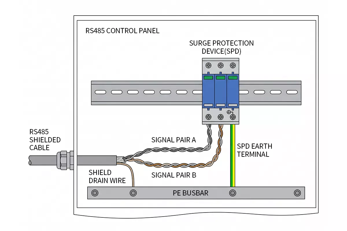
Figure 6 — Correct RS485 SPD earth lead routing: short lead to PE busbar, separated from signal cables, shield grounded at control room end only
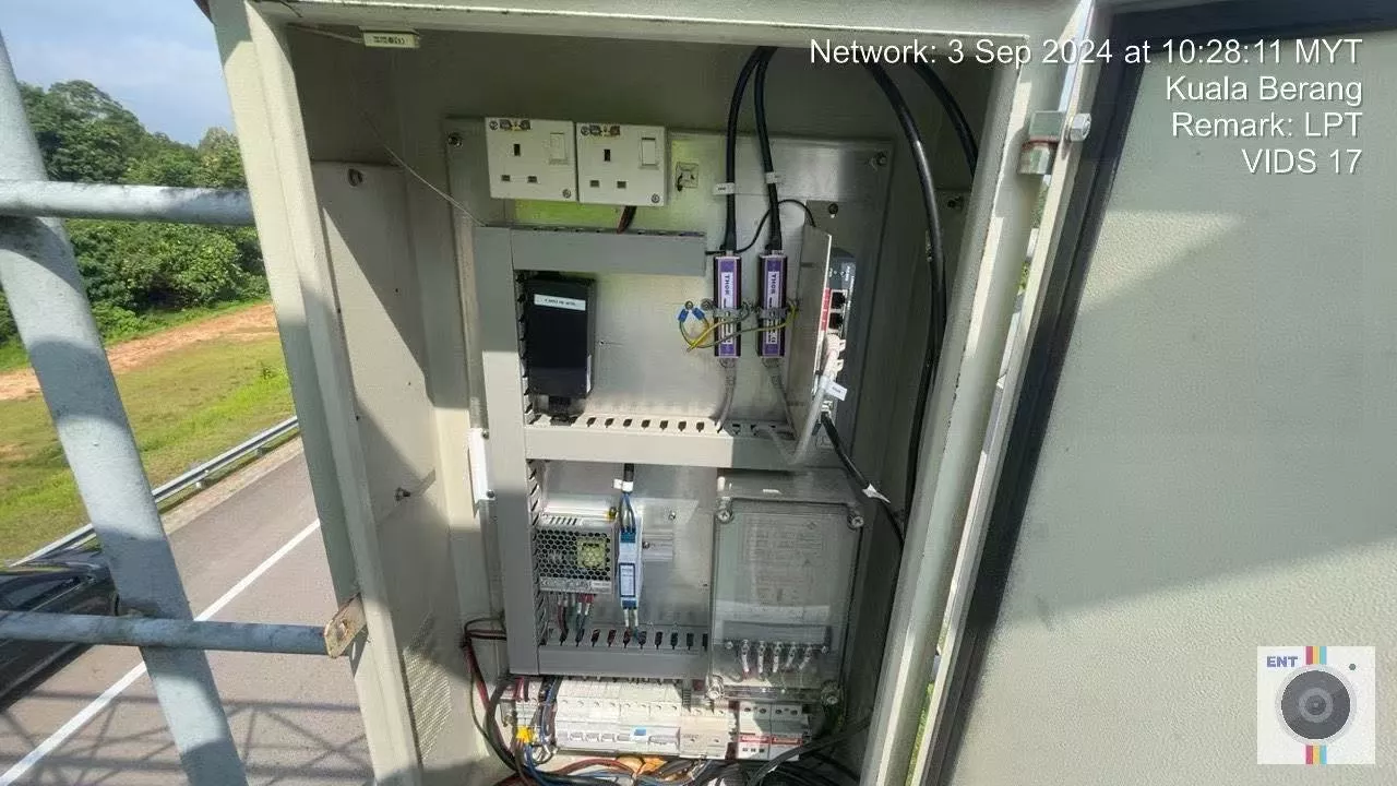
Figure 7 — Outdoor enclosure with RS485 and RJ45 surge protection devices installed at a remote field site, representing a typical far end installation
FAQ
Does RS485 differential signaling eliminate the need for surge protection?
No. RS485 differential signaling rejects noise that appears equally on both conductors, but it does not protect against common-mode surges caused by ground potential rise. When a lightning strike raises the ground potential at one end of the cable by thousands of volts, that voltage overwhelms the transceiver’s common-mode range of −7 V to +12 V regardless of the differential signal quality. Install an IEC 61643-21 compliant SPD at the cable entry point — that’s the standard specifically written for this class of device.
Where should I install an RS485 surge protector?
Install the SPD at the cable entry point of every enclosure where the RS485 line enters from an exposed environment. For runs crossing buildings, outdoor cable trays, or separate grounding domains, install at both ends — near end at the control panel and far end at the remote field device. Mount the SPD as close to the cable gland as possible and bond the earth terminal directly to the local PE busbar.
What voltage rating should I choose for an RS485 surge protector?
Select a device whose Uc exceeds the RS485 signal voltage in your system. For 24 V Modbus RTU or PLC I/O systems, use a device with Uc 30 V. For 12 V building automation networks, use Uc 15 V. For long-distance legacy SCADA links running at 100 V, use Uc 110 V. A Uc value too close to the signal voltage causes partial conduction during normal operation, degrading signal integrity and shortening service life.
Can I use an AC power SPD on an RS485 signal line?
No. AC power SPDs are tested and rated to IEC 61643-11, which covers power frequency waveforms and clamping voltages in the kilovolt range. RS485 signal line SPDs are rated to IEC 61643-21, which covers data line waveforms and clamping voltages in the tens of volts. An AC power SPD on an RS485 line will either fail to clamp at the right voltage or clamp so aggressively that it corrupts the signal during normal operation.
How do I know if my RS485 SPD needs replacement?
Check the visual indicator on the device — a red window or tripped indicator means the internal protection component has reached end of life and the device no longer protects the line. Also inspect after any confirmed lightning event near the site, even if the indicator remains green. Schedule visual inspections as part of routine panel maintenance.
What is the difference between RS485 surge protection and RS485 isolation?
An RS485 isolator breaks the galvanic connection between two segments of the bus, eliminating ground loops entirely. An SPD keeps the galvanic connection intact but diverts surge current to earth before it reaches the transceiver. Isolation is the stronger solution where ground potential differences are large and persistent — such as connections between buildings with separate power supplies. Surge protection is the correct solution where isolation is impractical or where the system requires continuous bus connectivity. In high-risk installations, both measures are used together.
Thor Electric RS485 Surge Protection Devices
Thor Electric manufactures the TRSS-485 series of DIN rail-mounted RS485 surge protection devices, certified to EN/IEC 61643-21. The series covers system voltages from 5 V to 100 V, with In 5 kA, Imax 10 kA, cutoff frequency 30 MHz, and insertion loss ≤ 0.5 dB — suitable for Modbus RTU, BACnet, and industrial sensor networks. All Thor Electric SPDs are certified to IEC, TUV, CE, RoHS, CB and ISO standards. Samples and OEM configurations are available.
Contact Thor Electric to discuss your project requirements.