Overvoltage protection is what separates a functioning installation from a repair bill. Lightning-induced transients last microseconds. Network faults can sustain power-frequency overvoltage for seconds. Both damage equipment — through different mechanisms, at different energy levels, requiring different responses. A correctly specified SPD handles the transient. The wrong one, or the right one wired badly, lets the voltage through.
What Is Overvoltage Protection?
Overvoltage protection covers the devices and methods that keep voltage in a power system within limits that connected equipment can survive. In low-voltage AC and DC installations, the primary tool is the surge protective device (SPD) — a parallel-connected component that conducts surge current to earth the moment voltage exceeds its threshold, then returns to standby. SPDs come in three types: Type 1 for direct lightning exposure, Type 2 for conducted and induced surges, Type 1+2 for both. Pick the wrong type and you have a device that was never tested for the threat it faces.
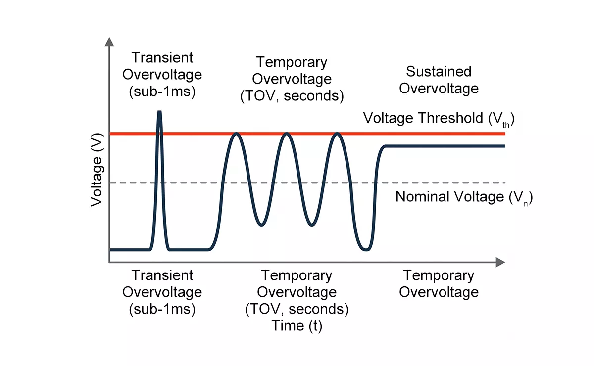
Figure 1 — Transient, temporary, and sustained overvoltage compared by duration and magnitude
What Causes Overvoltage in Power Systems?
Overvoltage events fall into three categories by origin.
Lightning is the most severe source. A direct strike on a building or overhead line injects current in the hundreds of kiloamperes range, generating voltage peaks that travel through the supply network. Indirect strikes — lightning hitting ground or structures nearby — induce voltage through electromagnetic coupling across cables running in the affected zone. Either mechanism produces transients well above the impulse withstand level of unprotected equipment.
Switching operations on the distribution network generate conducted transients every time a transformer energises, a capacitor bank switches, or a motor starts or stops. Per IEEE C62.41 low-voltage surge environment data, these switching transients typically reach 2–4 times nominal voltage. At 230V nominal, that puts peak switching transients in the 460–920V range — occurring far more frequently than lightning, and cumulative in their effect on MOV-based SPDs over time.
Network faults produce a different class of problem: temporary overvoltage (TOV). In a TT earthing system, a neutral conductor disconnection or MV/LV transformer insulation failure can cause a sustained power-frequency overvoltage on the affected phase. IEC 60364-4-44 defines the TOV stress level for TT systems as UT = 1.45 × U0 — at 230V nominal, approximately 333V sustained for up to 5 seconds. In TN systems the figure drops to UT = 1.1 × U0, or roughly 253V. An SPD that cannot withstand its system’s TOV level will fail thermally rather than protect.
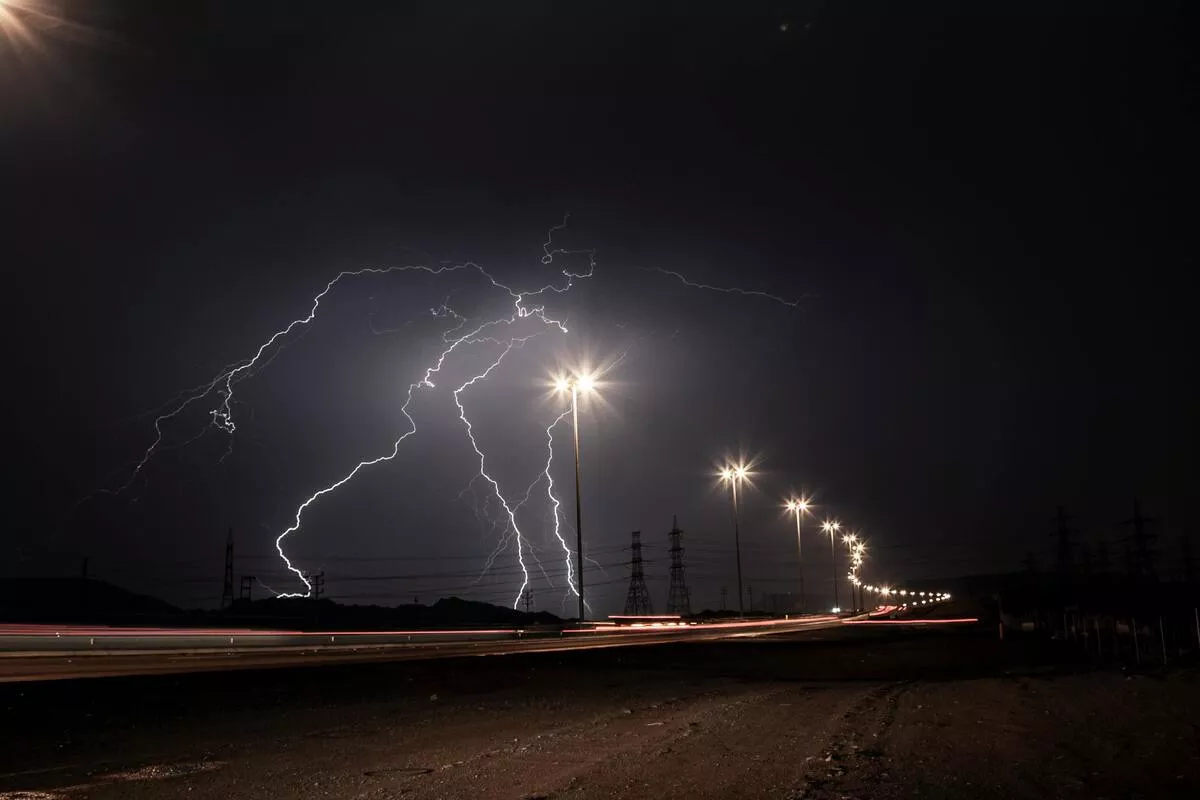
Figure 2 — Lightning strike on overhead power lines, a primary source of transient overvoltage in distribution networks
Alt text: Lightning strike on overhead power lines causing transient overvoltage in distribution network
Three Types of Overvoltage You Need to Know
As shown in Figure 1, overvoltage events differ significantly by duration, magnitude, and the protection mechanism required to handle them.
| Type | Duration | Typical Cause | SPD Relevance |
| Transient | < 1ms | Lightning, switching operations | Primary SPD design target |
| Temporary (TOV) | Milliseconds to seconds | Neutral fault, MV/LV insulation failure | Defines UT withstand requirement |
| Sustained | > seconds | Equipment fault, wrong transformer tap | Outside SPD scope |
Transient overvoltage lasts less than one millisecond. It is the primary threat SPDs are designed for, and the test waveforms used to classify them — 8/20µs for Type 2, 10/350µs for Type 1 — both represent this event class. The 10/350µs waveform carries approximately 20 times more energy than the 8/20µs waveform at the same peak current. The energy gap between waveforms is why Type 1 and Type 2 SPDs are not interchangeable on current rating alone — a Type 2 device exposed to direct lightning strike current will fail, not because it is inferior, but because it was never tested for that energy level.
Temporary overvoltage sits at power frequency (50 or 60Hz) and can persist for several seconds. SPDs do not clamp TOV the way they clamp transients. Instead, they must survive the TOV exposure without conducting or failing thermally. The UT parameter on an SPD datasheet is the TOV withstand rating — it must match the earthing system of the installation. A mismatch here is a common and costly specification error.
Sustained overvoltage is a steady-state condition caused by equipment faults or incorrect transformer tap settings. Surge protective devices are not rated for sustained conditions — that falls to voltage regulators, automatic tap changers, and upstream protection relays. If your system has a sustained overvoltage problem, an SPD is the wrong tool.
Overvoltage vs Overcurrent Protection: What’s the Difference?
Overvoltage protection (OVP) and overcurrent protection (OCP) address different failure modes and require different devices. Confusing the two — or assuming one covers the other — leaves part of your installation unprotected.
Overcurrent protection disconnects a circuit when current exceeds a safe level for the conductor or load. Fuses, MCBs, and RCDs operate on this principle. The fault they address is excess current flow, typically from a short circuit or overload. An MCB rated at 16A trips when sustained current draw exceeds its thermal or magnetic threshold.
Overvoltage protection works on a different mechanism entirely. An SPD does not interrupt the circuit. It conducts in parallel — diverting surge current to earth — while the main circuit stays live. The SPD’s job is to clamp the voltage spike before it reaches the load, not to disconnect the supply. Once the transient passes, the SPD returns to its high-impedance standby state automatically.
Response time is where the distinction becomes critical. A microsecond-duration voltage spike is over before an MCB’s thermal element has registered anything. SPDs respond in nanoseconds — Thor’s TRS series, for example, responds in under 25ns. Nanosecond response is the only reason an SPD can intercept a transient before it damages downstream equipment.
Both protections are required in any properly designed installation, and they work together. IEC 61643-11 requires an overcurrent protective device (OCPD) in series with every SPD installation — not to protect the load from the SPD, but to disconnect the SPD safely in the event of an SPD short-circuit failure. The MCB protects the SPD. The SPD protects the load. Neither replaces the other.
How an SPD Handles Transient Overvoltage
The core component in most AC and DC SPDs is the metal oxide varistor (MOV) — a voltage-dependent resistor that sits at very high impedance under normal operating voltage and switches to low impedance the instant voltage exceeds its clamping threshold. The impedance switch happens in under 25 nanoseconds. The surge current takes the low-impedance path through the MOV to earth, bypassing the load entirely. Figure 3 illustrates the clamping action — the incoming voltage spike is intercepted and the residual voltage reaching the load is the SPD’s rated Up (voltage protection level).
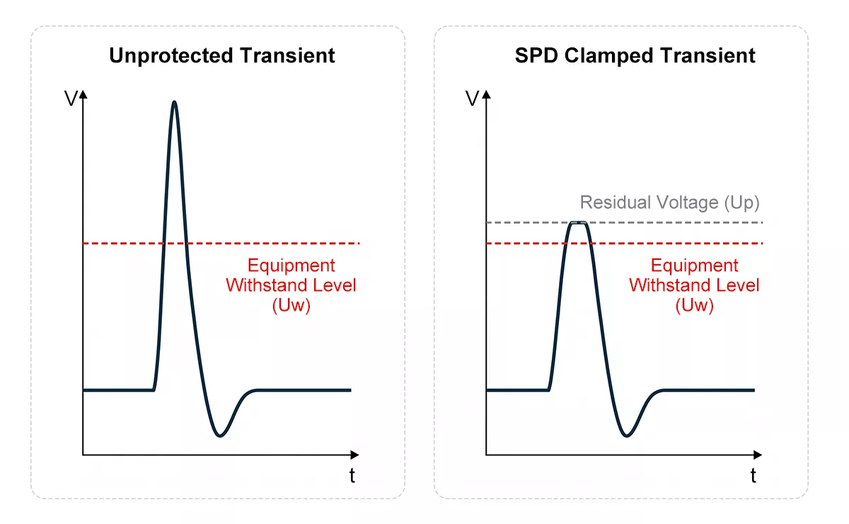
Figure 3 — SPD clamping action showing incoming transient voltage and residual voltage Up at load terminals
Up is not the voltage at which the SPD activates — it is the maximum residual voltage the SPD allows through during a rated surge event. For equipment protection to work, Up must sit below the impulse withstand voltage of the connected load. IEC 60664-1 defines impulse withstand categories: Category II equipment — the class covering most industrial control gear, drives, and switchgear inputs — has an impulse withstand of 2.5kV at 230V nominal. A Type 2 SPD with Up ≤1.5kV leaves a 1kV margin. Shrink that margin through poor installation and the protection disappears.
Lead length is the most common way that margin disappears. See Figure 6 for correct and incorrect installation.
DC Overvoltage Protection: Solar and Battery Systems
DC systems face the same overvoltage threats as AC installations — lightning induction, switching transients, and network faults — but the exposure geometry is different, and the selection rules change accordingly.
In a solar PV system, string cables running 100–300 metres across open ground act as efficient antennas for lightning-induced electromagnetic pulses. A nearby strike, not a direct hit, can induce transient voltages well above the DC input withstand level of the inverter. On the AC side, switching transients from the utility grid travel back through the inverter into the DC circuit. Most string inverters have no galvanic isolation between DC and AC stages, so both sides need independent overvoltage protection.
The key selection parameter for DC overvoltage protection is Ucpv — the maximum continuous operating voltage the SPD can sustain without conducting. Set it too low and the SPD activates under normal operating voltage, overheats, and fails within months. The correct calculation is:
Ucpv ≥ 1.1 × Voc(STC)
Voc(STC) is the string open-circuit voltage at 25°C. The 1.1 multiplier provides a minimum 10% margin for temperature variation — silicon cells produce higher Voc as temperature drops, so a string measuring 1000V at 25°C may reach 1100V or above on a cold morning.
Type selection follows the same logic as AC systems. Rooftop PV installations without an external lightning protection system (LPS) require a Type 2 DC SPD at the combiner box. Ground-mount systems in high keraunic zones — areas exceeding 25 thunder days per year — require a Type 1+2 DC SPD, tested to the 10/350µs waveform that represents direct lightning strike energy.
Thor’s TRS3-C40 covers Ucpv from 600V to 1800V DC across U-type and Y-type configurations, with In 20kA and Imax 40kA, certified to IEC 61643-31. For installations requiring Type 1+2 protection, the TRS3-C40 High Module variant covers Type 1+2 protection for 1000V DC systems.
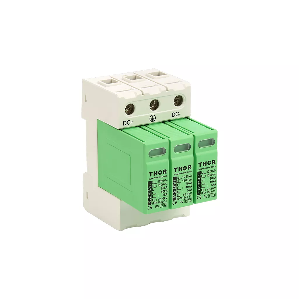
Figure 4 – Thor TRS3-C40 DC PV SPD, IEC and TUV certified
Battery storage and EV charging systems require DC overvoltage protection at lower voltage ranges — 24V, 48V, 110V DC depending on system architecture. The selection principle is the same: Uc must exceed the maximum DC bus voltage under all operating conditions, including charge termination voltage at low ambient temperatures.
Selecting an Overvoltage Protection Device: Key Parameters
Choosing an overvoltage protection device comes down to four parameters. Get all four right and the SPD does its job for years. Miss one and you have a device that either fails prematurely or never activates when needed.
Uc — Maximum Continuous Operating Voltage
Uc is the highest voltage the SPD can sustain indefinitely without conducting. It must be set above the maximum steady-state voltage the system can produce — including TOV conditions. For a 230V TN system, Uc ≥253V covers the UT = 1.1 × U0 TOV requirement. For a TT system, Uc ≥333V covers the higher UT = 1.45 × U0 stress level defined in IEC 60364-4-44. Thor’s TRS series is available in Uc 275V and 320V variants for standard European network configurations, with custom Uc options including 385V and 420V for higher-voltage applications.
Up — Voltage Protection Level
Up is the residual voltage across the SPD terminals during a rated surge event — the voltage that actually reaches the protected equipment. It must sit below the impulse withstand voltage of the load. For Category II equipment at 230V nominal, the IEC 60664-1 impulse withstand threshold is 2.5kV, so an SPD with Up ≤1.5kV provides adequate margin. Lower Up is better, but only if the SPD is installed with short lead lengths — a device rated Up ≤1.0kV installed with 1 metre of lead wire delivers far more than 1.0kV to the load in practice.
In and Imax — Discharge Current Ratings
In is the nominal discharge current — the peak current the SPD handles repeatedly without degradation, tested 15 times in sequence. Imax is the single-event maximum. For Type 2 AC SPDs in most industrial and commercial installations, In 20kA and Imax 40kA covers the majority of applications. Higher-exposure locations — service entrances, rooftop installations, sites near overhead lines — warrant Imax 60kA or above.
UT — Temporary Overvoltage Withstand
UT is the TOV level the SPD survives without thermal failure. As shown in Figure 5, a neutral disconnection fault in a TT system creates a sustained power-frequency overvoltage on the unfaulted phase — the scenario IEC 60364-4-44 uses to define the UT requirement.
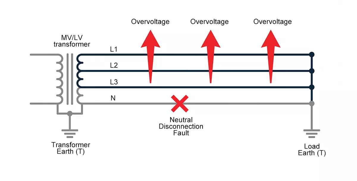
Figure 5 — Neutral disconnection fault in a TT system causing temporary overvoltage on the unfaulted phase
Match UT to your earthing system before specifying any SPD. An SPD with UT = 334V installed in a TT system meets the requirement. The same device in a TT system with UT = 275V does not — it will conduct and fail thermally during a neutral fault event before the upstream protection has time to clear the fault.
Lead Length — The Installation Parameter That Overrides Everything
Correct parameter selection means nothing if the SPD is wired incorrectly. Figure 6 shows the difference between a compliant and a non-compliant installation.
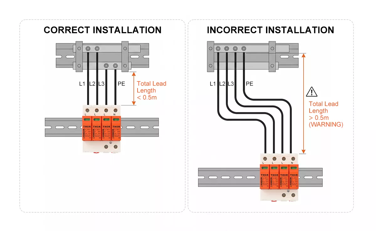
Figure 6 — Correct vs incorrect SPD lead length installation, total conductor length L1+L2+L3 must not exceed 0.5m
Every metre of conductor between the SPD terminals and the protected circuit adds approximately 1µH of parasitic inductance. At a lightning current rise rate of 10kA/µs, that generates 10kV of additional voltage on top of the SPD’s rated Up. Keep total lead length — line plus earth conductor combined — below 0.5 metres. Beyond that threshold, the installation negates the SPD’s rated protection level regardless of how well the device itself is specified.
Thor’s TRS4-C40 and TRS-B60 Type 2 AC SPDs cover the most common industrial specification requirements — In 20–30kA, Imax 40–60kA, Up ≤1.5–1.8kV, certified to IEC 61643-11. For DC and PV applications, the TRS3-C40 covers system voltages from 600V to 1800V DC under IEC 61643-31.
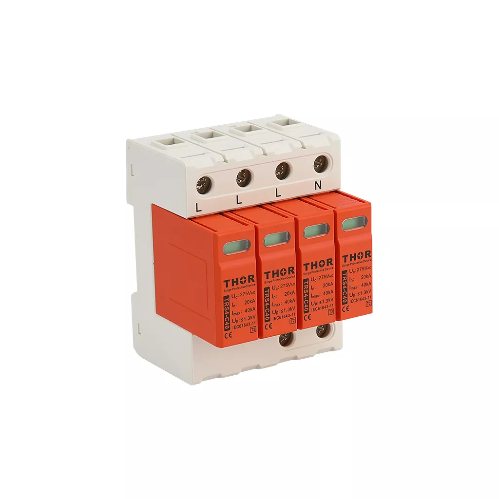
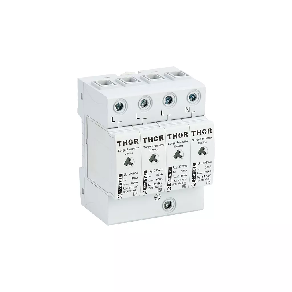
Figure 7 — Thor TRS4-C40 and TRS-B60 Type 2 AC SPD, IEC and TUV certified
FAQ
What is the difference between overvoltage protection and surge protection?
The terms refer to the same function in low-voltage power systems. Surge protection and overvoltage protection both describe the process of limiting transient voltage spikes before they reach connected equipment. The device used — a surge protective device (SPD) — is classified under IEC 61643-11 for AC systems and IEC 61643-31 for DC and PV systems. In everyday engineering use, the terms are interchangeable.
What devices are used for overvoltage protection?
In low-voltage AC and DC power systems, the primary overvoltage protection device is the SPD. Type 1 SPDs are rated for direct lightning strike energy at service entrances and main distribution boards. Type 2 SPDs handle conducted and induced transients at sub-distribution boards and equipment panels. Type 1+2 combined devices cover both in a single unit. For signal and data lines, dedicated signal line SPDs protect Ethernet, RS485, coaxial, and other communication circuits separately from the power system.
How do I know if my SPD is still working?
Most modern SPDs include a visual status indicator — a window that changes from green to red when the internal MOV has degraded beyond its service threshold. Thor’s TRS series uses a colour-coded indicator window visible from the front of the DIN rail mounting. For remote monitoring, the optional volt-free contact output signals SPD status to a building management system or control panel without interrupting the main circuit. If your SPD shows end-of-life indication, the modular cartridge can be replaced on-site without rewiring. The SPD aging and replacement guide covers the full end-of-life process in detail.
What is the difference between overvoltage protection and overcurrent protection?
Overcurrent protection — fuses, MCBs, RCDs — disconnects a circuit when current exceeds a safe level, typically from a short circuit or overload. Overvoltage protection intercepts voltage spikes without disconnecting the circuit. An SPD conducts in parallel, diverting surge current to earth while the load stays live, then returns to standby automatically. Both are required in a complete installation: IEC 61643-11 mandates an overcurrent protective device in series with every SPD to handle SPD short-circuit failure safely.
Does overvoltage protection work for DC systems?
Yes, but DC-specific SPDs are required. AC SPDs are not rated for DC applications — the arc suppression requirements differ, and an AC SPD used on a DC circuit may fail to interrupt follow current after a surge event. DC SPDs certified to IEC 61643-31 are designed and tested for DC systems, with Ucpv ratings covering common PV system voltages from 600V to 1800V DC. For battery storage and EV charging at lower voltages, DC SPDs are available from 24V to 110V DC system voltage.
Can an SPD protect against all types of overvoltage?
No. SPDs are designed for transient overvoltage — events lasting less than one millisecond. They are rated to survive temporary overvoltage (TOV) conditions such as neutral faults without failing, but they do not clamp TOV the way they clamp transients. Sustained overvoltage caused by equipment faults or incorrect transformer tap settings falls outside SPD scope entirely and requires voltage regulators or upstream protection relays. Matching the right protection device to the right overvoltage type is the starting point of any correctly specified installation.
Thor Electric Overvoltage Protection Devices
Thor Electric manufactures AC, DC, and PV surge protective devices covering Type 1, Type 2, and Type 1+2 classifications, certified to IEC 61643-11 and IEC 61643-31. Samples, custom Uc variants, and OEM configurations are available for project-specific requirements. Contact the Thor Electric team to discuss your installation.