
A temporary overvoltage (TOV) is a mains-frequency overvoltage that lasts from seconds to minutes — long enough to cook an SPD built only to divert microsecond surges. When a neutral is lost or a PEN conductor breaks, the voltage across your surge protector can climb toward 400 V and stay there. The SPD does not clamp it away. Its metal oxide varistor conducts, heats, and either disconnects safely or fails as a fire risk.
Riding out a TOV comes down to three things: enough Uc margin to survive the sustained voltage, a thermal disconnector that opens before the varistor ignites, and IEC 61643-11 TOV testing that proves the device fails safe. One point gets missed in the field — an SPD will not protect your downstream equipment from a prolonged TOV. That job belongs to voltage monitoring and disconnection. What a well-built SPD guarantees is that it takes itself out of the circuit without becoming the hazard.
What a Temporary Overvoltage Is — and Why It Isn’t a Surge
A temporary overvoltage (TOV) is a power-frequency overvoltage above an SPD’s rated voltage that lasts from seconds to minutes, usually caused by a system fault such as a lost neutral. Unlike a transient surge measured in microseconds, a TOV applies sustained thermal stress. An SPD is designed to divert surges — not to withstand or clear a prolonged overvoltage.
The distinction matters because it decides what your protection can and can’t do. A surge is a fast, high-energy spike: a lightning transient rises and decays in tens of microseconds, and the SPD’s varistor clamps it, absorbs the energy, and returns to a high-impedance state. That whole event is over before a breaker senses anything.
A TOV behaves nothing like that. The voltage sits above normal for cycles, seconds, or minutes — a duration the varistor was never sized to conduct through. Instead of one short pulse of energy, the MOV faces a continuous power feed it has to dissipate as heat. Sources range from utility faults and load switching to ferroresonance, but the one that turns up most in low-voltage installations is the loss of a neutral or PEN conductor. That case gets its own section, because it’s where most field failures start.
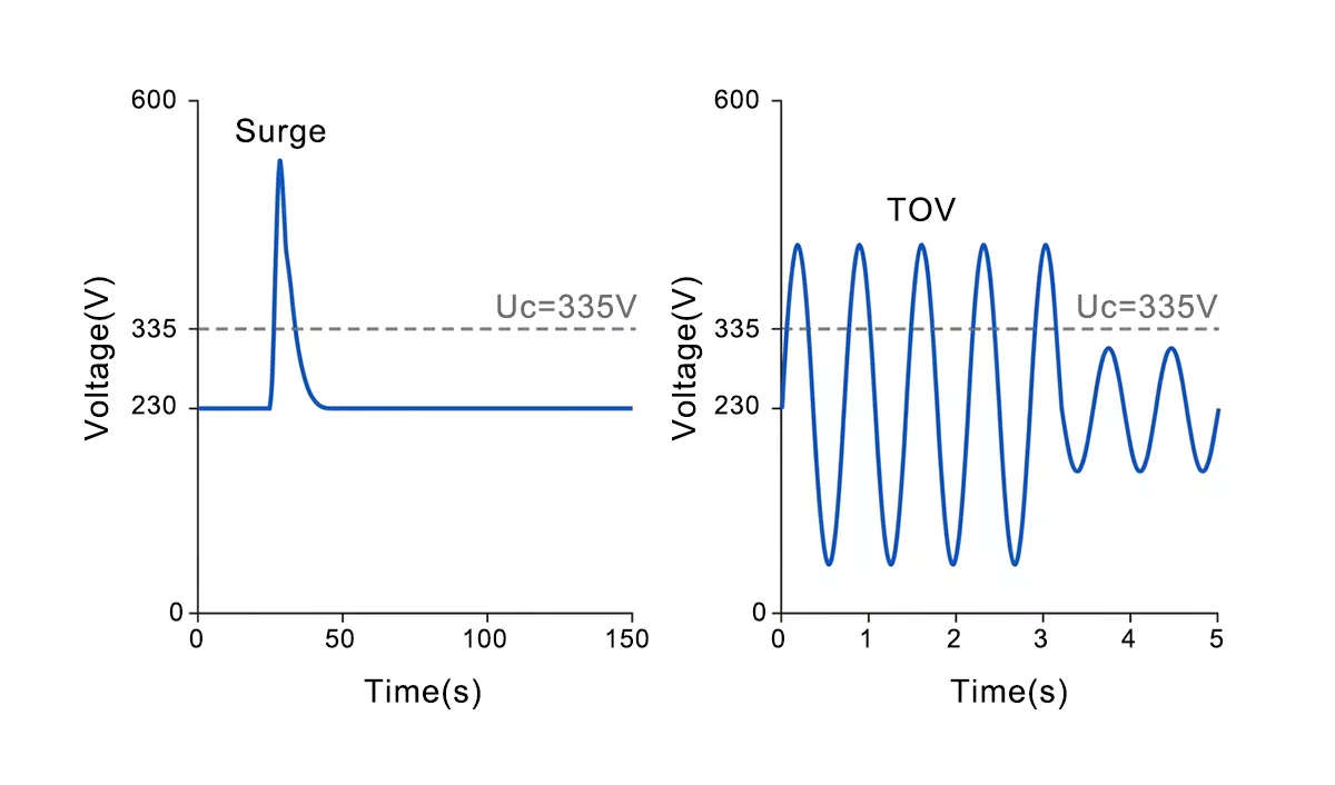
Figure 1 — Transient surge vs temporary overvoltage — microsecond spike compared to a sustained mains-frequency overvoltage above *Uc*.
Loss of Neutral: The TOV That Catches Most Installations Out
Most TOV events in low-voltage systems trace back to one fault: a broken neutral. In a TN-C-S earthing system — the arrangement the UK calls PME — the incoming service shares a single PEN conductor that splits into separate neutral and protective earth at your main earthing terminal. Everything downstream references that split point. Break the PEN upstream of it, and the reference floats.
Here’s what that does electrically. Under balanced load, the neutral sits near earth potential and each phase reads its nominal 230 V to neutral. Lose the neutral and the star point of the load is no longer tied down. It drifts toward the most heavily loaded phase, and the lightly loaded phases climb in the opposite direction. On a single-phase supply the effect is blunter but no safer — an open neutral leaves the load in series across two lines, and voltage divides by impedance rather than by design.
The numbers are what make this dangerous for an SPD. IEC 61643-11 models the loss-of-neutral case at 1.45 × U₀ — about 335 V on a 230 V system. Under a badly unbalanced load the lightly loaded phase can push further, toward the full line-to-line 400 V, and hold there until the utility clears the fault. That can be minutes. A varistor rated for 275 V continuous is now sitting in a sustained 335–400 V field with no surge to divert — just a steady overvoltage it has to survive or fail out of.
As shown in Figure 2, the load star point shifts off earth once the neutral opens, dragging the lightly loaded phase voltages up.
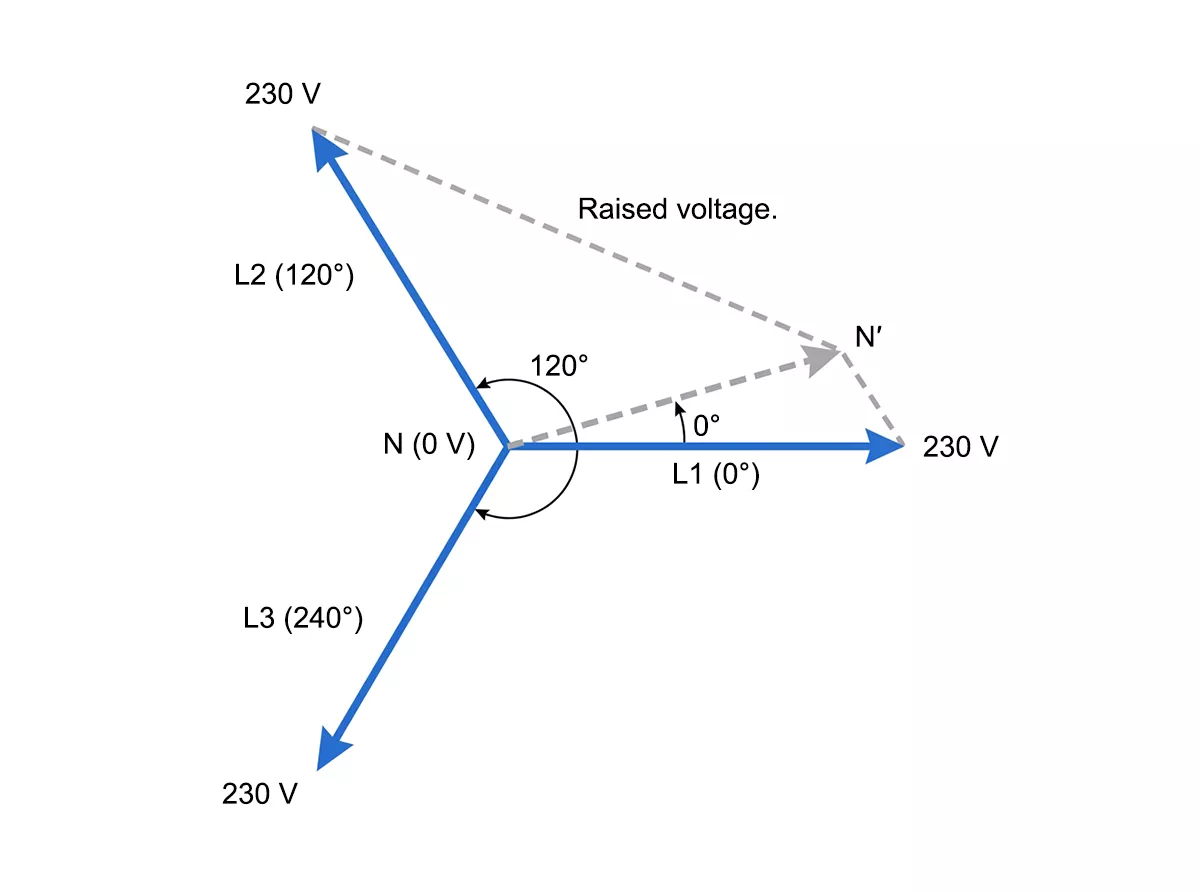
Figure 2 — Neutral-point shift during a loss-of-neutral fault — the star point floats toward the heavily loaded phase, raising voltage on the others.
We see this in roughly one in three retrofit projects. Corrosion at an overhead joint, a loosened terminal in a service head, mechanical damage to a buried cable — the supply keeps working right up until it doesn’t, and nothing trips. No overcurrent, no earth fault the breaker can see. The first sign is often equipment failing across the site at once, or an SPD’s fault indicator going red.
What a TOV Does to Your SPD — Victim, Not Protector
During a normal surge, the MOV inside your SPD earns its keep. The transient exceeds the varistor’s clamping voltage, current flows for microseconds, energy dissipates, and the MOV returns to its high-impedance resting state. The whole event dumps a fraction of a joule. The varistor barely warms.
A TOV reverses every part of that sequence. The voltage across the MOV exceeds its maximum continuous operating voltage Uc — not for microseconds but for seconds or minutes. The varistor enters a low-impedance state and stays there, conducting milliamps to amps of power-frequency current the entire time. Energy dissipation is no longer a brief pulse; it becomes a continuous heat source inside a sealed plastic housing.
What happens next depends on the margin between the TOV and Uc, and on how the SPD is built to fail.
If the TOV sits just above Uc — say 290 V against a 275 V-rated varistor — the leakage current rises from microamps into the milliamp range. The MOV heats. Its resistance drops with temperature, which draws more current, which generates more heat. This is thermal runaway: a positive feedback loop that accelerates until something interrupts it.
A well-designed SPD interrupts it with a thermal disconnector — a spring-loaded contact that opens when the varistor housing reaches a set temperature, pulling the MOV off the circuit before ignition. We test every pluggable module’s disconnector at the varistor’s rated trip temperature — the contact opens cleanly before the housing reaches ignition point. The fault indicator flips to red, the optional remote-signal contact changes state, and the SPD is electrically dead but physically safe. That is a controlled end-of-life, not a failure.
An SPD without adequate thermal protection — or one where the TOV is so far above Uc that the disconnector can’t react fast enough — does not get that clean exit. The varistor overheats to the point of decomposition, the zinc-oxide disc cracks, tracking currents carbonise the housing, and the result is a short-circuit arc or fire inside the panel. At that point the upstream breaker or fuse clears the fault, but the damage is done.
Figure 3 traces both paths: sustained conduction above Uc, thermal runaway, and the branch between safe disconnection and catastrophic failure.
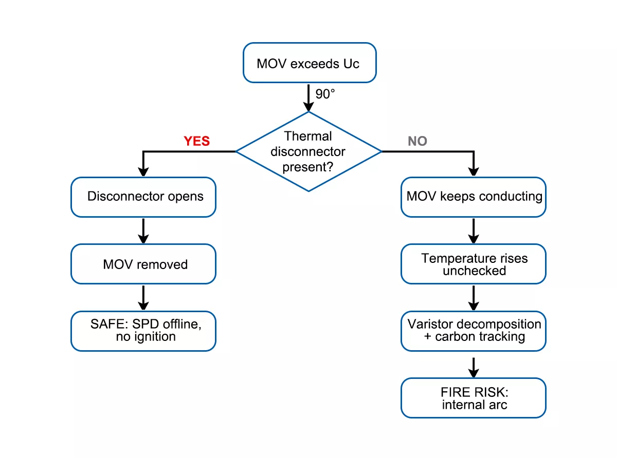
Figure 3 — MOV behavior during a temporary overvoltage — thermal disconnector path (safe) vs thermal runaway path (fire risk).
The critical takeaway: an SPD does not protect the load from the TOV itself. While the varistor conducts, the voltage across the terminals barely drops — it clamps at the varistor’s conduction voltage, not at a safe operating level. Downstream equipment still sees an elevated voltage for the full duration of the fault. The SPD’s only role in a TOV event is to not make things worse — to take itself offline without becoming an ignition source. Protection of the load requires a separate voltage monitoring relay or undervoltage/overvoltage disconnector upstream of the equipment.
How IEC 61643-11 Tests for Temporary Overvoltage
IEC 61643-11 does not leave TOV survival to guesswork. The standard defines a specific test parameter — UT, the rated temporary overvoltage — and spells out what “passing” looks like: the SPD either rides out the overvoltage and keeps working, or it disconnects itself without flame, without arc, and without creating a new hazard.
The test simulates the loss-of-neutral condition directly. For a 230 V system the applied voltage is 1.45 × U₀, roughly 335 V RMS at 50 Hz, held for 5 seconds across each protection mode. That duration is short compared to what a real open PEN can last, but it is long enough to push a marginal varistor into thermal runaway if the design lacks headroom.
Two outcomes are acceptable under the standard. In the first, the SPD withstands the overvoltage and remains functional — its protection level unchanged, ready for the next surge. In the second, the SPD’s internal disconnector operates: the varistor is taken offline, the device signals end-of-life through its fault indicator, and no external flame or sustained arcing occurs. Both outcomes are a pass. What fails the test is anything in between — a varistor that stays connected while overheating, a housing that ignites, or a device that creates a short-circuit fault the backup protection was not sized to clear.
For TT systems the standard adds a harder test: 1200 V AC between N and PE for 200 ms at 300 A, simulating a high-voltage fault migrating from the MV network. That test specifically validates the N-PE spark gap (typically a GDT) in a CT2-wired SPD — a scenario where the PEN is not a factor, but the TOV magnitude is far more severe. If you specify SPDs for TT installations, check whether the device carries this additional UT rating, not just the standard 5-second figure.
One detail worth flagging: UT in the datasheet is a single-event rating. It proves the device can survive one TOV of that voltage for that duration. It does not promise survival after repeated events, and it does not mean the SPD will protect load equipment during the overvoltage. The SPD’s job under TOV is binary — stay safe or get out. Load protection is a separate layer.
Selecting and Installing SPDs for TOV Resilience
The engineering lever you control is Uc margin — the gap between the SPD’s maximum continuous operating voltage and the temporary overvoltage the system can produce. A wider margin means lower leakage current during a TOV, slower heating, and more time for the thermal disconnector to act before anything critical happens.
On a 230 V TN-S or TN-C-S system, a Uc of 275 V is the industry baseline. That gives a ratio of 1.20 × U₀ — workable under normal mains fluctuations, but thin against a full loss-of-neutral TOV at 1.45 × U₀ (335 V). The varistor is already conducting hard at that voltage. Stepping up to a 320 V Uc variant pushes the ratio to 1.39 × U₀, which buys meaningful thermal headroom: lower conduction current, slower temperature rise, and a disconnector that trips on its own terms rather than racing a runaway.
There is a trade-off. Raising Uc raises the voltage protection level Up — the clamping voltage the load actually sees during a surge. A 275 V-rated Type 2 MOV might clamp at 1.0–1.5 kV; the same design at 320 V clamps higher. For most industrial loads with a 2.5 kV impulse withstand rating that increase is insignificant. For sensitive electronics closer to their withstand limit, it needs checking against the equipment’s immunity spec before you commit.
In most installations we support, the 320 V Uc variant covers the loss-of-neutral case with margin — the higher Up stays well within the 2.5 kV impulse withstand of standard industrial loads. We endurance-test our 320 V Uc modules well past the 5-second IEC requirement: 200 cycles at 335 V confirms the disconnector trips on thermal protection, not on panic.
Beyond Uc selection, three hardware features separate an SPD that fails safely from one that doesn’t:
Thermal disconnector. A spring-loaded contact that opens when the varistor housing reaches its rated temperature. Non-negotiable for any SPD installed on a system where neutral loss is physically possible — which, in practice, is every TN-C-S supply.
Visual fault indicator. A red/green window on the module face that shows at a glance whether the disconnector has operated. After a TOV event the SPD may look physically intact from the outside. Without a status indicator, a dead module sits in the panel offering zero protection until someone tests it.
As shown in Figure 4, a red indicator window means the thermal disconnector has operated — green means the module is still live and protecting the circuit.
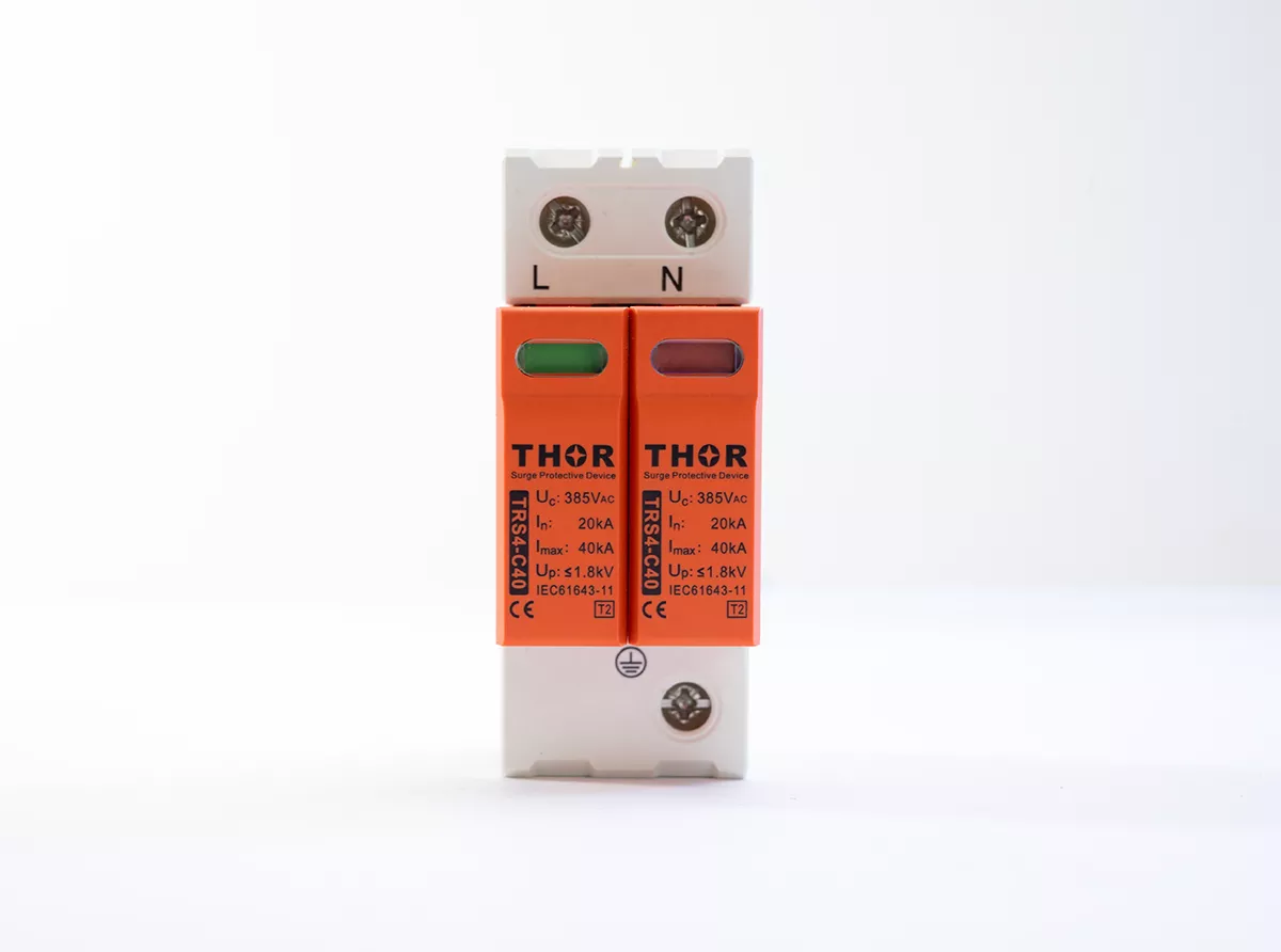
Figure 4 — SPD fault indicator comparison — red (disconnector tripped, end-of-life) vs green (normal operation).
Remote signalling contact. A volt-free changeover contact (typically 250 V / 0.5 A) wired back to a BMS or alarm panel. In unstaffed sites — substations, pumping stations, rooftop PV arrays — nobody walks past the distribution board to check a window. The remote contact is the only way the TOV-induced failure gets noticed before the next surge arrives to an unprotected circuit.
Figure 5 shows Thor TRS Type 2 AC and DC pluggable modules with the fault indicator window and remote signalling terminal visible.
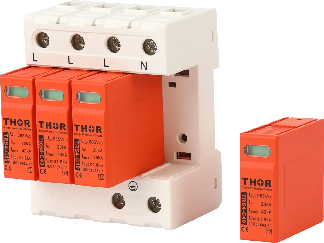
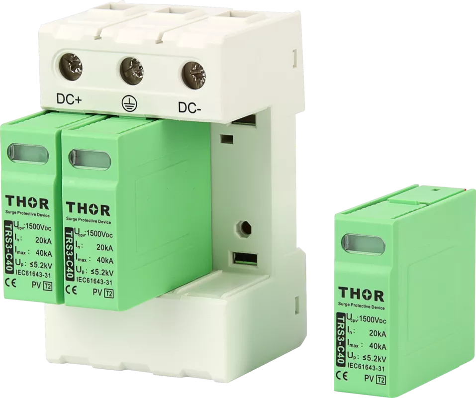
Figure 5 — Figure 4. Thor TRS AC and DC Type 2 SPD modules — pluggable design with visual fault indicator and remote signalling contact.
What the SPD Cannot Do
An SPD will not clear the TOV, will not regulate voltage back to nominal, and will not protect your load equipment during the event. Once the thermal disconnector trips, the SPD is offline — the overvoltage is still present on the bus until the upstream fault is resolved. A tripped module is end-of-life: it cannot be reset and must be replaced. Until a new module is fitted, the circuit has zero surge protection.
Protecting the load requires a voltage monitoring relay (sometimes called an overvoltage/undervoltage disconnector, or OVDP) wired to trip the main contactor or incoming breaker when the supply drifts outside tolerance. For sites where PEN integrity is a persistent concern — older overhead networks, coastal areas with corrosion risk, long rural feeders — converting the installation from TN-C-S to TT earthing with a local electrode removes the dependency on the PEN conductor entirely.
| Fault scenario | Voltage at SPD | SPD response | What protects the load |
| Normal mains (230 V ±10%) | ≤ 253 V | High-impedance standby | Not needed |
| Moderate TOV (swell, 1.1–1.2 × U₀) | 253–276 V | Slight leakage rise, no trip | Mains tolerance; no action needed |
| Loss of neutral, balanced load | ~335 V (1.45 × U₀) | Thermal disconnector trips; SPD offline | Voltage monitoring relay / OVDP |
| Loss of neutral, heavy imbalance | Up to ~400 V | Rapid disconnector trip or thermal runaway risk | Voltage monitoring relay + upstream breaker |
| TT MV fault (N-PE) | Up to 1200 V, 200 ms | GDT spark gap fires (CT2 wiring) | RCD + overcurrent device |
Figure 6 shows how the SPD, voltage monitoring relay, and upstream breaker work together during a TOV event — the SPD handles surge duty only, while the relay and breaker form the overvoltage protection layer.
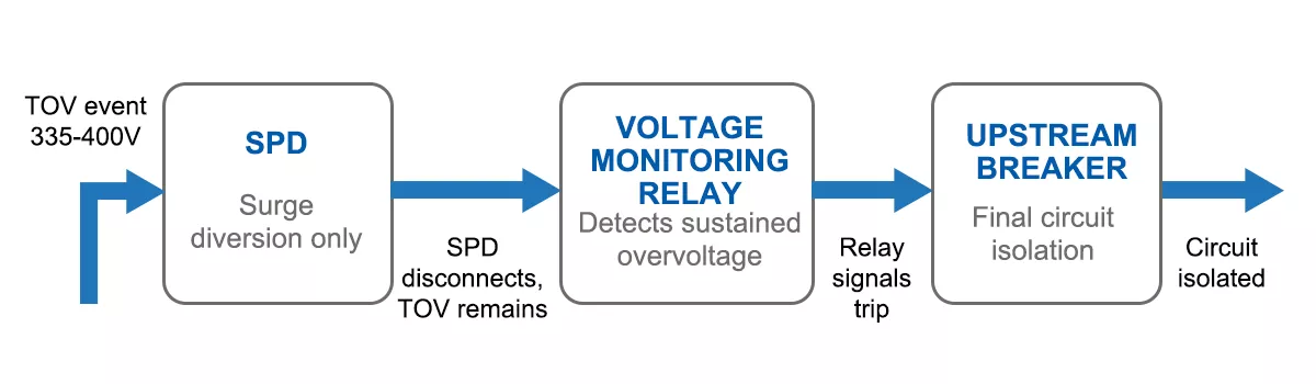
Figure 6 — TOV protection coordination — SPD for surge diversion, voltage monitoring relay for sustained overvoltage disconnection, upstream breaker for final isolation.
FAQ
Can an SPD protect equipment from a temporary overvoltage?
No. An SPD diverts transient surges measured in microseconds — it is not designed to regulate or clear a sustained power-frequency overvoltage. During a TOV the varistor conducts continuously and eventually disconnects itself. The load remains exposed to the elevated voltage until a separate device — a voltage monitoring relay or overvoltage disconnector — trips the supply.
What is the difference between a surge and a temporary overvoltage?
A surge is a fast transient lasting microseconds to milliseconds, typically caused by lightning or switching. A temporary overvoltage is a mains-frequency event lasting seconds to minutes, usually caused by a system fault such as a lost neutral. The SPD clamps a surge and returns to standby. A TOV forces the SPD into sustained conduction and thermal stress — two completely different failure modes from the same device.
How does a lost neutral cause overvoltage on an SPD?
In a TN-C-S system the neutral and protective earth share a single PEN conductor upstream of the main earthing terminal. If that conductor breaks, the load star point floats. Lightly loaded phases see their line-to-neutral voltage climb toward the full line-to-line value — up to 400 V on a 230 V system. That voltage sits across the SPD continuously, exceeding its rated Uc and driving the MOV into thermal conduction.
Does IEC 61643-11 require SPDs to survive a TOV event?
IEC 61643-11 tests every SPD against a rated temporary overvoltage UT. For a 230 V system the test applies 1.45 × U₀ (roughly 335 V) for 5 seconds. The SPD must either withstand the voltage and remain functional, or disconnect safely with no flame or sustained arc. Any outcome between those two — a varistor that stays connected while overheating — is a test failure.
Thor Electric Surge Protection Devices
Thor Electric manufactures IEC- and TUV-certified SPDs across AC, DC, PV, and signal-line applications. All pluggable-module series include a thermal disconnector, visual fault indicator, and optional remote signalling contact — the three features that determine whether an SPD fails safely under a temporary overvoltage event. Samples, custom Uc variants, and OEM supply are available. Contact us to discuss your project requirements.