
Most SPD datasheets lead with the biggest number on the page, and for a Type 2 device that number is usually Imax. Of all the SPD parameters printed on the sheet, it is close to the least useful one for comparing products. IEC 61643-01:2024 lists Imax at item 28 of its marking and information list, worded “if declared by the manufacturer”, while item 6 requires a Type 2 SPD to declare In in kA. The headline figure is optional. The one describing whether the device survives more than a single event is mandatory.
The sections below work through the SPD parameters that decide a purchase, in the order they should change your mind: Uc first, then Up, then the three current ratings that look comparable and are not. They also cover something no supplier datasheet mentions, which is that the standard defining these terms changed in 2025.
What the SPD parameters on a datasheet mean
An SPD datasheet describes one device with about a dozen symbols, and five of those SPD parameters carry most of the selection weight: Uc is the voltage the SPD tolerates continuously, Up is the voltage that still reaches your equipment, and In, Imax and Iimp are three different current capabilities measured under three different tests. Everything else qualifies those five.
| Symbol | Name | Unit | What it decides |
| Uc | Maximum continuous operating voltage | V | Whether the SPD survives your system at rest |
| Up | Voltage protection level | kV | What your equipment is exposed to during a surge |
| In | Nominal discharge current, Type 2 test | kA | Whether it survives repeated surges |
| Imax | Maximum discharge current | kA | The single-event ceiling, optional declaration |
| Iimp | Impulse discharge current, Type 1 test | kA | Direct lightning current capability |
| UT | Temporary overvoltage test value | V | Behaviour when the mains itself goes wrong |
| Isccr | Short-circuit current rating | kA | Whether it fails safely at your fault level |
Read the table from the right-hand column. A parameter matters to you only through the decision it gates, and two devices with identical Imax can differ on every other line.
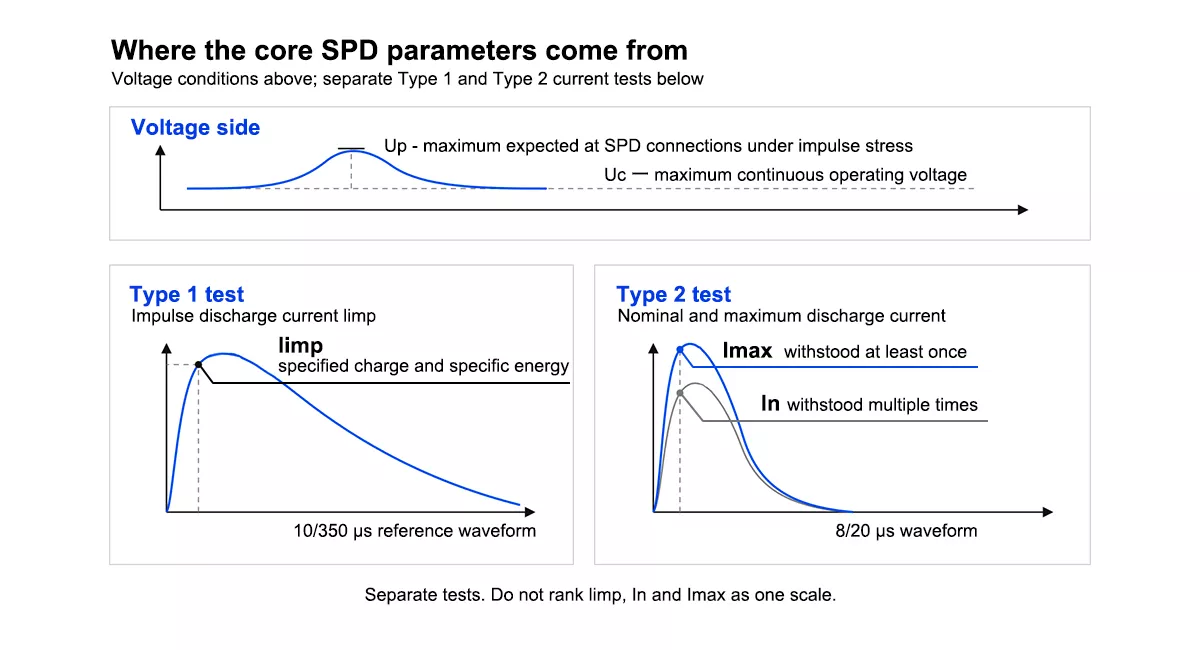
Figure 1 — Where each of the core SPD parameters comes from: *Uc* and *Up* on the voltage side, and *Iimp*, *In* and *Imax* measured under separate Type 1 and Type 2 tests.
Which standard defines these parameters, and what changed in 2025
Nearly every page explaining SPD parameters tells you they are defined in IEC 61643-11. That was true until June 2025.
IEC 61643-11:2025 reached edition 2.0 in June 2025, and the revision moved the general requirements out. Clause 3 of the current edition says that Clause 3 of IEC 61643-01 applies, and adds exactly one new term of its own. Clause 5 is marked Void. The definitions of Uc, Up, In, Imax and Iimp now live in IEC 61643-01:2024, the base standard published in December 2024, and IEC 61643-11 holds only what is specific to AC power systems. The vocabulary moved with them: what IEC 61643-11:2011 called a Class I, II or III test is now defined as a T1, T2 or T3 SPD, which is why current devices carry T1, T2 or T3 in a square rather than a class number.
For a buyer this is not trivia. A supplier claiming conformity to IEC 61643-11 is quoting half the picture, because the general requirements and the parameter definitions sit in the base standard. The useful question is which edition of each document the test evidence covers.The standard number alone is not enough; the model, declared ratings and applicable edition should also match the supporting test evidence. Our guide to verifying an SPD certificate explains how to check that scope before purchasing.
One more check costs nothing. Across the IEC 61643 family, parts ending in 1 are requirements and test methods, and parts ending in 2 are selection and application principles. A conformity claim should cite a requirements-and-test part, because those are the ones a device is tested against. IEC 61643-12 is application guidance for designing an installation, not a product test standard, so a datasheet citing it as the basis of certification has pointed at the wrong document. That is worth noticing before the technical discussion goes any further.
Uc: the parameter that decides whether the SPD survives your system
Of all the SPD parameters, Uc is the one that decides whether the device survives being installed at all. It is the highest voltage that can sit across the SPD indefinitely. IEC 61643-01:2024 puts it plainly in its service conditions: the voltage applied continuously between the SPD connections shall not exceed Uc.
Set it too low and the SPD can sit under continuous overstress rather than waiting for a surge, drawing leakage current, running warm and ageing early while the installation behaves perfectly. Nothing about that failure looks like a surge event, which is why it gets written off as a faulty product. Going higher is not automatically safer either, since Uc has to be weighed against the Up it comes with and the TOV behaviour declared for the device.
The mapping is straightforward once system voltage is fixed:
| System | Typical *Uc* | Thor series |
| 230 V AC single phase | 275 V AC | TRS4 |
| 230/400 V AC three phase, L-PE | 275 V AC | TRS4 |
| 380 V AC | 385 V AC | TRS7 |
Headroom above nominal is deliberate. It absorbs the voltage regulation of the supply, which IEC 61643-01 asks the manufacturer to declare as a percentage at item 10 of its information list. On networks with wide swings, or where the neutral is unreliable, the next step up is worth evaluating against the Up and TOV consequences. We build the TRS4 range in both 275 V and 320 V Uc versions for that reason, and Thor can supply 420 V, 385 V and 320 V variants where the network calls for it.
Up: what your equipment actually sees
Up is the most quoted of the SPD parameters and the most often misread. IEC 61643-01:2024 defines it at 3.1.75 as the maximum voltage to be expected at the SPD connections under a defined impulse stress. It is not the residual voltage, which the standard lists separately as Ures. Lower is better, and Up is the figure to compare against the impulse withstand rating of whatever sits downstream.
The words doing the work are “at the SPD connections”. Up describes the device on its own. In an installation, the connection leads add inductance, and the voltage arriving at the equipment is the Up of the SPD plus whatever those leads contribute. Lead inductance is the reason for the familiar guidance to keep SPD connections short: slack cable can give back the advantage a lower-Up device was bought for.
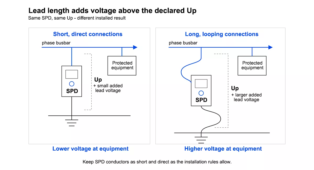
Figure 2 — Connection lead length adds inductive voltage on top of *Up*, so the voltage reaching the equipment is higher than the datasheet figure.
There is a second trap, and our own range demonstrates it honestly. Across the Thor TRS4 range, Up climbs as discharge capability climbs: the TRS4-D20 holds Up to `≤1.0 kV` at In 10 kA, the TRS4-C40 to `≤1.5 kV` at In 20 kA, and the TRS4-B60 to `≤1.8 kV` at In 30 kA. Bigger is not automatically better. A device chosen purely for current capability can expose sensitive electronics to a higher let-through voltage than a smaller one would.
That trade-off is why coordinated SPD protection uses more than one protection stage rather than one oversized device at the origin.
Item 11 of the information list in IEC 61643-01:2024 adds a detail worth quoting at suppliers. The manufacturer may supply a discharge-current versus protection-level curve, and the note singles out the value at 5 kA as being of interest for IEC 60364-5-53 applications. Asking for Up at 5 kA rather than the headline number tells you a great deal about who you are dealing with.
Three current ratings that do not compare
Here is where most specifications go wrong, and the official names of the symbols give the game away. In IEC 61643-01:2024, Iimp is the impulse discharge current for the Type 1 test, and In is the nominal discharge current for the Type 2 test. The test class is inside the name. These are results of different experiments, not three sizes of one quantity.
- In is the repeated-duty rating, measured with an 8/20 µs waveform. It answers whether the device survives a surge and is still there for the next one.
- Imax is the single-event ceiling on the same 8/20 µs waveform. It answers what the device can take once.
- Iimp is measured with a 10/350 µs waveform, which simulates direct lightning current. That waveform carries far more energy than an 8/20 µs pulse of the same peak, so a Type 1 device rated in the low tens of kA Iimp is handling a much harsher event than a Type 2 rated far higher in Imax.
Comparing a Type 1 Iimp figure against a Type 2 Imax figure is comparing two different tests, which is why these three SPD parameters cannot be ranked against each other. The larger number is not the stronger device.
Now the part that changes how you read a quotation. IEC 61643-01:2024 sets out what must be declared, and for discharge parameters item 6 is specific: a Type 1 SPD declares Iimp in kA, a Type 2 SPD declares In in kA, and a Type 3 SPD declares Uoc in kV. Imax appears separately at item 28, qualified with “if declared by the manufacturer”.
The definitions say the same thing. IEC 61643-01:2024 defines a T2 SPD at 3.1.70.2 as one tested with the nominal discharge current In; Imax does not appear in the definition of the device class at all. Of the three current SPD parameters, only In decides what a Type 2 device is.
So the number most Type 2 datasheets put in the largest font is the optional one. In is the required declaration, and In is also the rating that describes durability rather than a single survivable hit. When two Type 2 SPDs both advertise 40 kA, the question that separates them is what each declares for In. Our TRS4-C40 declares In 20 kA alongside Imax 40 kA; a device claiming the same Imax on a much lower In is a different product wearing a similar headline.
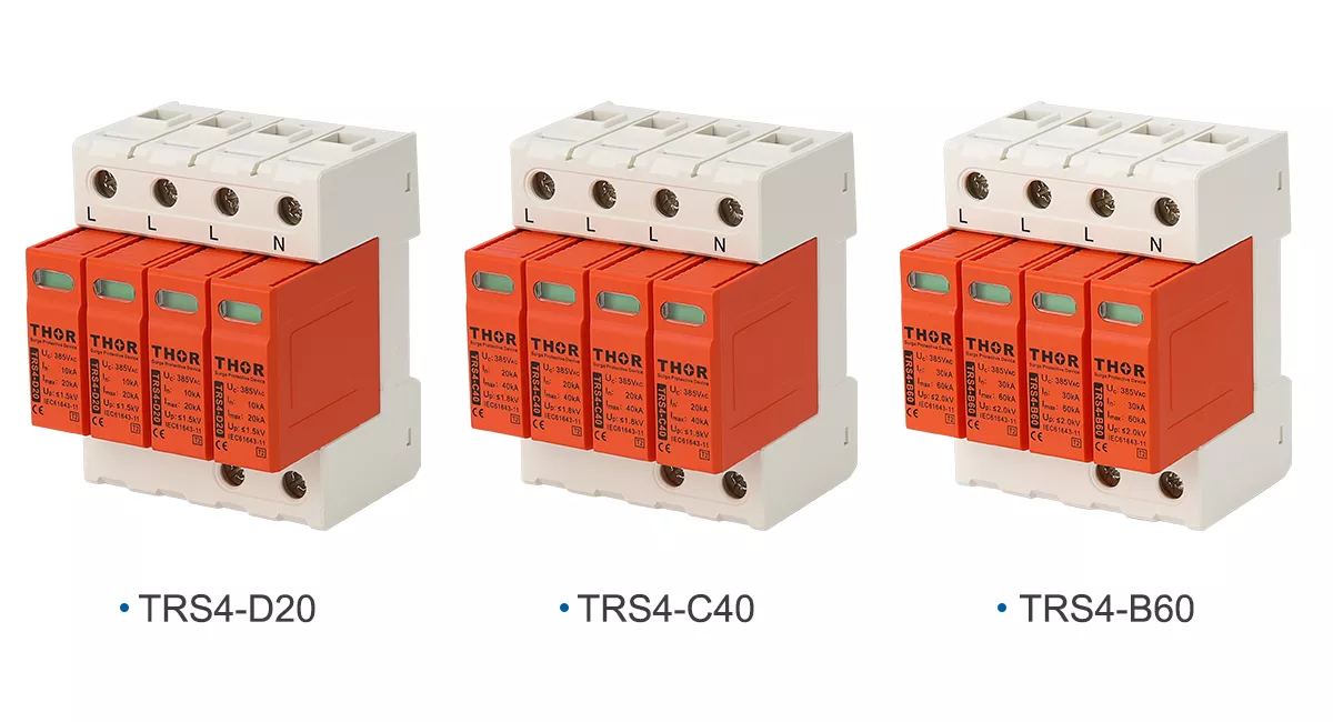
Figure 3 — The Thor TRS4 Type 2 range side by side: TRS4-D20, TRS4-C40 and TRS4-B60. As *In* rises from 10 kA to 30 kA, *Up* rises with it, from `≤1.0 kV` to `≤1.8 kV`.
TOV and SCCR: the two parameters buyers skip
Two SPD parameters get skipped in almost every comparison, and both decide what happens when things go badly wrong. Temporary overvoltage is the supply itself failing: a lost neutral, a fault bleeding from the medium-voltage side. The SPD sees a raised power-frequency voltage for seconds or minutes, which is a completely different stress from a microsecond surge.
Competing explanations of TOV quote durations, and they disagree with each other. There is a reason for that. IEC 61643-01:2024 lists the TOV application time for testing as being set in clause 9.3.9 of the subsequent parts, and the note against item 30 says test values and details sit in the relevant subsequent part. No single duration applies across the family.
What the base standard does require is a declaration. Under item 30 the manufacturer states the TOV test value UT, the corresponding fault currents or system types, and the TOV behaviour, which is either withstand or safe end-of-life. That binary is the useful question. Either the device rides the event out, or it disconnects without creating a hazard. IEC 61643-11:2025 carries the same requirement for AC systems, and notes that it covers the fault-protection requirements of 534.4.6 of IEC 60364-5-53:2019+AMD1:2020.
TT systems deserve one extra line. An SPD that the manufacturer declares suitable for installation between neutral and PE upstream of the main RCD has to pass the medium-voltage TOV test in withstand mode. If your design puts a device in that position, the declaration is what you verify, not the marketing copy.
Isccr, the short-circuit current rating, is the other quiet one. It is the maximum prospective short-circuit current at which the SPD, combined with the external disconnector specified by the manufacturer, has been tested to behave safely. It has to meet or exceed the prospective fault current at the point of installation. Item 18 of the information list requires the ratings of that backup disconnector to be declared alongside, and the pair only means something together.
IEC or UL? Why the same parameter has two names
Search results on SPD parameters and specifications mix two standards families, which is how readers end up comparing numbers that were never measured the same way.
| IEC 61643 term | Nearest UL 1449 term |
| Up, voltage protection level | VPR, voltage protection rating |
| Uc, maximum continuous operating voltage | MCOV, maximum continuous operating voltage |
The pairs are counterparts, not equivalents. Each standard defines its own test and its own declaration rules, so a VPR figure and a Up figure are not interchangeable on a comparison sheet. If a quotation mixes the two vocabularies, ask which standard each of the SPD parameters was declared under before comparing anything.
Joule ratings belong to neither. They are a consumer outlet-strip metric and appear nowhere in the IEC 61643 information list, so a supplier answering a technical question with a joule figure is answering a different question.
Thor datasheets use the IEC parameter vocabulary throughout this article. IEC, TUV, CE, RoHS, CB and ISO coverage varies across the portfolio, so verify the certificate scope and standard edition for the quoted model.
What IEC requires on the SPD and in the datasheet
A datasheet is not a marketing document under this standard. The SPD parameters on it are declared items: IEC 61643-01:2024 sets out a list of 43 marking and information items in Clause 6.2, each required only where it applies to the device in question, and IEC 61643-11:2025 divides that list into tiers according to where each item has to appear.
| Where it appears | Items | Contents |
| Visible after installation | 1 to 3 | Manufacturer name or trademark and model number; SPD type marked T1, T2 or T3 in a square; indication of disconnector operation |
| On the SPD body | 4 to 8 | Uc per mode of protection; type of current; the declared discharge parameter; identification of connections including PE; rated load current for two-port devices |
| Declared by the manufacturer, if applicable | 1 to 40 | Everything above plus Up, Isccr, system type and overvoltage category, backup disconnector ratings, temperature range, end-of-life mode, TOV declaration and the rest |
| For type testing | 41 to 43 | Mode of protection design, test standards for status-indication circuits, overstress test current |
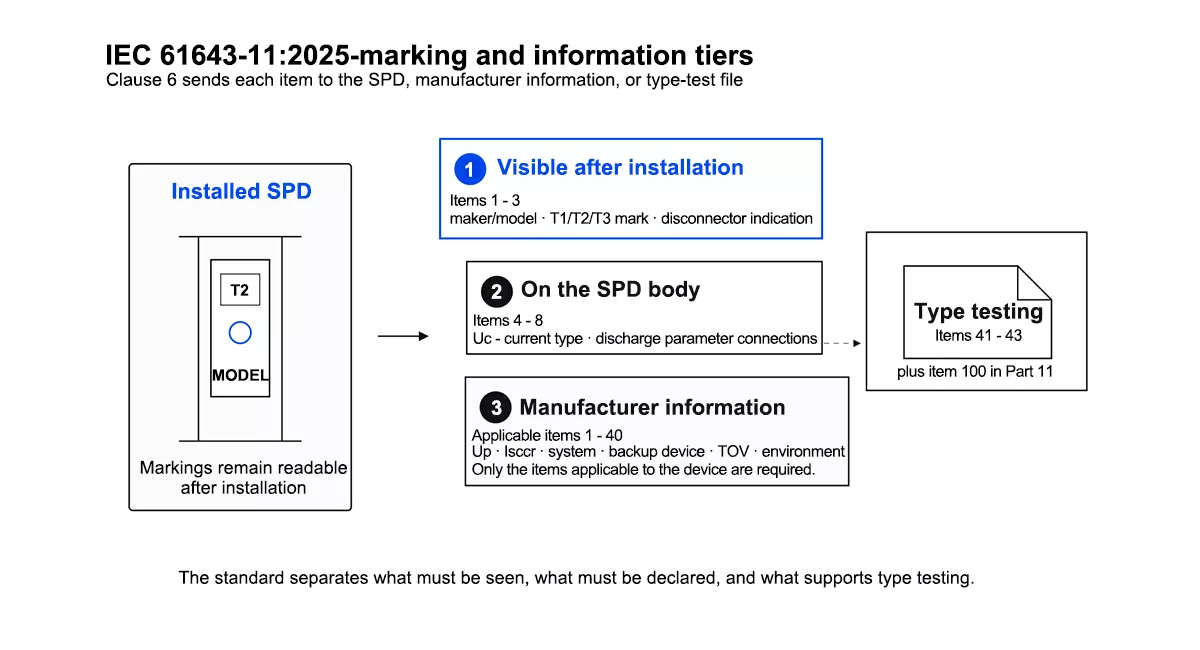
Figure 4 — IEC 61643-11:2025 splits SPD information into tiers: a few markings that must stay visible after installation, more on the body, and a much longer declared list in the datasheet.
Two practical consequences follow. First, a device that has been installed should still show you its maker, its model, its boxed type marking and its status indication, because those are the items required to stay visible. If a panel inspection cannot recover that, the installation cannot be verified. Second, not every item applies to every device, but a specification sheet running to five lines is still nowhere near what the standard contemplates a manufacturer declaring. Asking which of the items apply, and for the ones that do, is a reasonable request rather than an awkward one.
Clause 6.1 adds a fairness rule for combined devices. An SPD may be classified as more than one type, and where the manufacturer declares a single protection level for such a device, it has to be the highest one. That matters when comparing a Type 1+2 device against a Type 2, because the declared Up is not describing the same thing in both cases.
Six questions come straight out of these clauses:
- Your Type 2 datasheet headlines Imax. What is the declared In under item 6?
- Can you supply Up at 5 kA, per the note to item 11, rather than only the headline value?
- Under item 30, is the declared TOV behaviour withstand, or safe end-of-life?
- Item 20 asks for system types and overvoltage category. Which TN, TT or IT systems is this designed for?
- What are Isccr and the backup disconnector ratings required by item 18?
- The device is declared Type 1+2. Under Clause 6.1, is the declared Up the highest of its modes?
Worked example: choosing protection for a distribution board
The SPD parameters fall into place in a fixed order once the system is known. Take a sub-distribution board on a 230/400 V TN-S system in a building with no external lightning protection system, feeding general loads and a small amount of instrumentation.
Step 1, type. Take it as given for this example that a risk assessment and the local installation rules have already settled on a Type 2 device at this board. Type selection depends on the risk assessment, the installation rules in force and the protection already upstream, not on the presence or absence of an LPS by itself. Our comparison of Type 1 vs Type 2 vs Type 3 SPD covers how the classes divide up.
Step 2, Uc. L-PE modes sit at 230 V nominal, so Uc 275 V AC gives working headroom. If the supply is known to run high, evaluate the 320 V version against its Up and TOV declaration.
Step 3, discharge rating. The design input for this example is In 20 kA with Imax 40 kA, taken from the project specification; the rating for a real board comes from the selection process in IEC 61643-12 together with the local installation rules. Whatever the target, read In first and treat Imax as the secondary figure.
Step 4, Up. At In 20 kA the Thor TRS4-C40 declares Up `≤1.5 kV`. Compare that against the impulse withstand of the equipment on the board, and remember to allow for the connection leads. Instrumentation needing a lower let-through voltage is usually better served by a local Type 3 stage than by fitting a larger device here.
Step 5, wiring configuration. TN-S takes a 3+1 arrangement on three-phase boards, or 1+1 on single phase, which places a device between neutral and PE and the phase modes between line and neutral. The SPD wiring diagram guide shows the arrangements in full.
Step 6, the backup device and the paperwork. Confirm Isccr meets or exceeds the prospective fault current at the board, fit the backup protection the manufacturer declares under item 18, and keep the declaration of TOV behaviour with the project records.
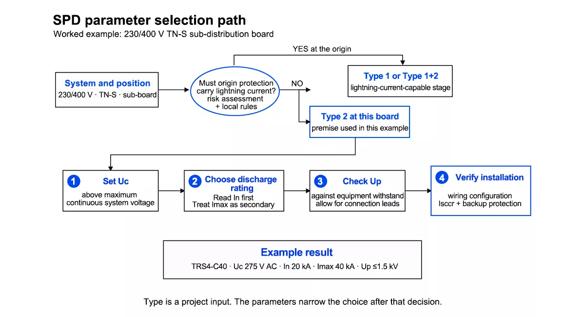
Figure 5 — Selection path for a 230/400 V TN-S board: project requirements set the SPD type, then *Uc*, discharge rating and *Up* narrow it to a model.
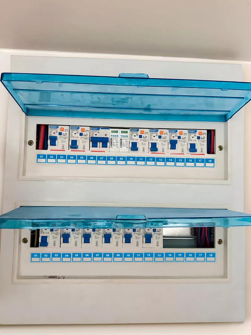
Figure 6 — Type 2 SPD on DIN rail in a distribution board, with the marking required by Clause 6 still readable after installation.
FAQ
What are the main SPD parameters on a datasheet?
The five that carry most selection weight are Uc, the maximum continuous operating voltage; Up, the voltage protection level; and In, Imax and Iimp, three discharge current ratings measured under different tests. UT for temporary overvoltage and Isccr for short-circuit rating decide safety behaviour. All are defined in IEC 61643-01:2024.
Is Imax or In the more important rating?
In. IEC 61643-01:2024 requires a Type 2 SPD to declare In in kA at item 6 of its information list, while Imax sits at item 28 as an optional declaration. In describes repeated-surge durability, whereas Imax is a single-event ceiling, so two devices sharing an Imax headline can differ substantially in In.
How do you calculate the right SPD rating?
Work through the SPD parameters in order rather than calculating a single figure. Establish the type from the risk assessment, installation rules and upstream protection, set Uc above the system’s maximum continuous voltage, choose the discharge rating from the installation’s exposure and position, then check Up against the impulse withstand of the protected equipment. Confirm Isccr meets or exceeds the prospective fault current last.
What is the 10 m rule for SPD?
It is application guidance rather than a rule in the product standard. The voltage reaching equipment rises with the length of conductor between it and the SPD, so beyond roughly 10 m an additional protection stage is often worth considering. Whether one is needed, and of which type, follows from the installation standard in force and the manufacturer’s coordination instructions. Lead length is not printed among the SPD parameters, but it changes what they deliver.
Is Up the same as VPR?
No. Up is the IEC 61643 voltage protection level and VPR is the UL 1449 voltage protection rating. They are standards-specific declarations, so the figures are not interchangeable between an IEC datasheet and a UL one without checking the applicable test evidence.
What does SCCR mean on an SPD datasheet?
Isccr, the short-circuit current rating, is the prospective short-circuit current at which the SPD together with its declared backup protective device has been tested to disconnect safely. It must meet or exceed the prospective fault current at the installation point, and unlike most SPD parameters it is only meaningful alongside the specified external disconnector the manufacturer declares with it.
Thor Electric SPD ranges
For AC systems, Thor Electric manufactures Type 1, Type 2 and Type 1+2 surge protective devices; the portfolio also includes DC, PV and signal-line SPDs. Browse the Type 2 AC SPD range when comparing models for sub-distribution boards. Certifications held across the portfolio include IEC, TUV, CE, RoHS, CB and ISO, and coverage varies by model, so ask for the certificate scope and standard edition for the specific part number you are quoting. The AC range covers Uc from 275 V to 385 V with In ratings from 5 kA to 100 kA, in pluggable modules with visual fault indication and optional remote signalling. Samples, full datasheets covering the declared SPD parameters, and OEM or ODM production are available. Contact our engineering team with your system voltage, earthing arrangement and installation position for a specification.