
Lightning protection system design under IEC 62305 runs in a fixed order: assess the risk, pick a protection level from that assessment, position the air termination, route the down conductors into an earth termination, then protect what is inside the building. Skip the first step and every number after it is a guess.
Most guides on this subject list the parts of a lightning protection system and stop there. What follows instead is the procedure itself, with the numbers the standard specifies and the arithmetic for two calculations you can run before anyone opens a spreadsheet.
What lightning protection system design decides
Lightning protection system design answers five questions in sequence: does the structure need protection, at which protection level, where the air terminations go, how the current reaches earth, and how the systems inside survive what gets through. IEC 62305-2 answers the first two, IEC 62305-3 covers the external system, IEC 62305-4 the inside.
The IEC 62305 series splits the job in two. For the component-level picture first, our guide to the lightning protection system walks through the parts themselves. An external lightning protection system, per the IEC 62305-3 introduction, does three things: it intercepts a flash to the structure with an air-termination system, conducts the current safely towards earth through a down-conductor system, and disperses it into the ground through an earth-termination system. An internal system prevents dangerous sparking inside the structure, using equipotential bonding or a separation distance between the external system and the building’s conducting parts.
Those two halves fail differently. An external system that works keeps the building from burning down. It does nothing for the switchgear, and a design that stops at the roof is half a design.
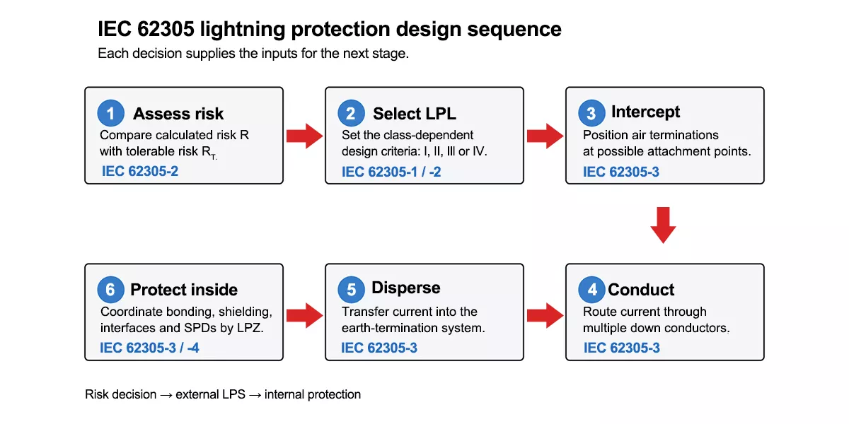
Figure 1 — The IEC 62305 design sequence, from risk assessment through to internal protection, showing which part of the standard governs each step.
Two terms recur and are worth fixing now. IEC 62305-1 talks about the lightning protection level (LPL) I to IV. IEC 62305-3 talks about the class of LPS, also I to IV. Its Table 1 maps them one to one, so a design at LPL II is built as a Class II LPS. Different documents, same four levels.
Step 1: risk assessment decides whether you need a system at all
Lightning protection system design starts before any hardware. IEC 62305-2 asks whether the risk R to the structure exceeds the tolerable risk RT. If it does not, the structure is adequately protected as it stands and no LPS is required. If it does, you identify which risk components are driving the number, select protection measures, and recalculate until R falls below RT.
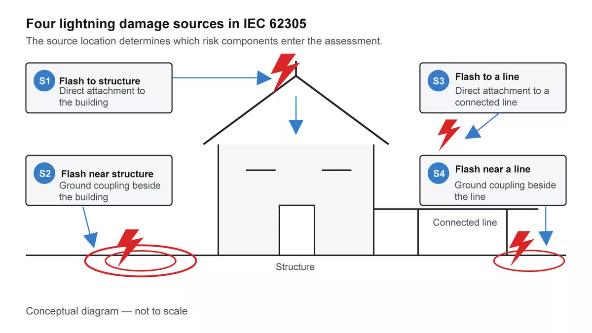
Figure 2 — The four sources of damage in IEC 62305: S1 flash to the structure, S2 flash near the structure, S3 flash to a connected line, S4 flash near a connected line.
Every risk component uses one equation. IEC 62305-2:2024 gives it as Equation (9):
`RX = NX × PX × LX`
NX is the number of dangerous events per year, PX the probability that such an event causes damage, and LX the consequent loss. Nine components (RAT, RAD, RB, RC, RM, RU, RV, RW and RZ) are all built from that one product, then summed per risk zone.
Working out the collection area
The part you can compute yourself is NX, and it starts with how much ground the building effectively collects strikes from. IEC 62305-2 Annex A defines the equivalent collection area AD as the area enclosed where a line of 1:3 slope, running from the top of the structure and rotating around it, meets the ground. For an isolated rectangular building of length L, width W and height H on flat ground, Equation (A.3) gives:
`AD = L × W + 2 × (3 × H) × (L + W) + π × (3 × H)²`
Take a 60 m × 30 m industrial building, 12 m to the roof:
| Term | Calculation | Area |
| Footprint | 60 × 30 | 1 800 m² |
| Sides | 2 × 36 × (60 + 30) | 6 480 m² |
| Corners | π × 36² | 4 071 m² |
| Total AD | ≈ 12 352 m² |
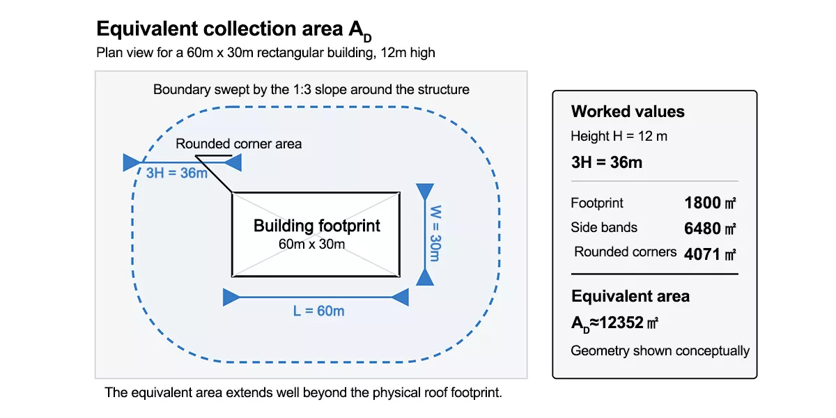
Figure 3 — Equivalent collection area: the 1:3 slope rotating around the building extends the area that collects strikes well past the footprint.
The footprint is 1 800 m². The collection area is about 6,9 times that. A building gathers strikes from well beyond its own walls, which is why floor area is a poor proxy for lightning exposure and why two buildings with identical footprints but different heights carry different risk.
Roof protrusions change the answer. Equation (A.4) gives the collection area of an elevated protrusion as `AD’ = π × (3 × HP)²`, and you take whichever is greater: that, or Equation (A.3) using the building’s minimum height. Put a 25 m stack on the same building and AD′ works out at roughly 17 671 m², so the stack governs the whole assessment.
Getting the strike density
The next input is the local lightning ground strike-point density NSG, in strike points per km² per year. IEC 62305-2 Annex A takes NSG from a lightning location system complying with IEC 62858. Where that is not available directly, Equation (A.1) scales ground flash density: `NSG = k × NG`, and the standard supplies its own fallback. Where the data provider cannot give you k, or where only a NG map exists for the country, a factor of 2 can be assumed. Where there is no ground-based location system at all, Equation (A.2) estimates `NSG = 0,5 × NT` from optically recorded total flash density.
Density and area together are still not an event count. Turning them into the annual number of dangerous events ND also takes the location factor CD, which accounts for the surroundings and for nearby objects that intercept strikes, plus a unit conversion, since NSG is expressed per square kilometre while AD comes out in square metres.
Where this stops
That is as far as you can honestly get with a calculator. Beyond CD, a risk figure needs the probability and loss tables in IEC 62305-2 Clause 8 and the tolerable risk values RT, and a real assessment usually partitions the structure into risk zones, each with its own numbers, before summing anything.
Which explains something you will have noticed while searching: the results for this topic are full of spreadsheets and software. That is not laziness. A full IEC 62305-2 assessment across four damage sources, nine risk components and multiple zones is genuinely a tooling problem. What you can do by hand is establish the collection area and understand what the tool is doing with it.
Step 2: the protection level sets the class-dependent design criteria
The risk assessment produces a lightning protection level, the single input that shapes the rest of the lightning protection system design. IEC 62305-1 is explicit that the LPL is normally selected as the result of that assessment. There is an exception worth knowing: the IEC 62305-3 introduction notes that national or local law can specify the required LPS class for particular applications without a risk assessment. Germany determines the need for protection and the LPS class through a national annex, with the IEC 62305-2 assessment as an option rather than the route. Buildings in the United States follow NFPA 780 instead, a different standard with its own structure. Check the local rules before running the numbers.
Lightning protection system design uses four levels, I to IV, each with a fixed set of maximum and minimum lightning current parameters. The maxima define what the system must survive. IEC 62305-1:2024 Table 3 gives them:
| Parameter | Symbol | LPL I | LPL II | LPL III | LPL IV |
| First positive short stroke, peak current | I | 200 kA | 150 kA | 100 kA | 100 kA |
| First positive short stroke, charge | QSHORT | 100 C | 75 C | 50 C | 50 C |
| First positive short stroke, specific energy | W/R | 10 MJ/Ω | 5,6 MJ/Ω | 2,5 MJ/Ω | 2,5 MJ/Ω |
| Subsequent short stroke, peak current | I | 50 kA | 37,5 kA | 25 kA | 25 kA |
| Subsequent short stroke, average steepness | di/dt | 200 kA/µs | 150 kA/µs | 100 kA/µs | 100 kA/µs |
| Long stroke, charge | QLONG | 200 C | 150 C | 100 C | 100 C |
| Flash, charge | QFLASH | 300 C | 225 C | 150 C | 150 C |
The first positive short stroke carries a 10/350 µs waveform. LPL I is the reference; LPL II sits at 75 % of it and LPL III and IV at 50 %, which is why the last two columns are identical. Time parameters do not change with level.
These numbers are not academic. IEC 62305-1 states directly that Table 3 is used to design lightning protection components: conductor cross-sections, metal sheet thicknesses, the current capability of SPDs, and separation distances against dangerous sparking. When a Type 1 SPD is rated Iimp 25 kA at 10/350 µs, that waveform and that current class trace back to this table.
So “what is level 4 lightning protection” has a concrete answer: LPL IV is the lowest of the four, designed against a 100 kA first positive stroke and a 60 m rolling sphere, and IEC 62305-1 Table 5 puts the probability that a flash stays within its limits at 0,95 on the maximum side and 0,84 on the minimum side. LPL I covers 0,99 at both ends.
The level fixes the class-dependent criteria: current parameters, rolling sphere radius, mesh size, down-conductor spacing. It does not fix everything. Structure geometry, soil resistivity, material choices and national rules all still move the lightning protection system design.
Step 3: positioning the air termination
Air-termination positioning is the part of lightning protection system design most people picture when they hear the phrase. It is what the flash attaches to instead of the roof. IEC 62305-3 accepts three methods for positioning it: rolling sphere, mesh, and protective angle. They are not alternatives so much as tools for different geometries.
The rolling sphere method is the one that generalises. IEC 62305-1:2024 Table 4 gives the radius for each level, derived from the minimum peak current the system is designed to intercept:
| Interception criteria | LPL I | LPL II | LPL III | LPL IV |
| Minimum peak current I | 3 kA | 5 kA | 10 kA | 16 kA |
| Rolling sphere radius r | 20 m | 30 m | 45 m | 60 m |
The standard states what this table is for: positioning the air-termination system, and defining the zone LPZ 0B that is protected against direct strikes. Roll a sphere of radius r over the structure. Wherever it touches, a flash can attach, and those points need an air termination. Wherever it cannot reach, the volume is protected.
The logic runs opposite to intuition. A stricter protection level uses a smaller sphere, and a smaller sphere rolls into places a large one bridges over. LPL I with its 20 m sphere finds attachment points on a roof that a 60 m sphere would sail across, which is why a high-risk building ends up with more air terminations, not fewer.
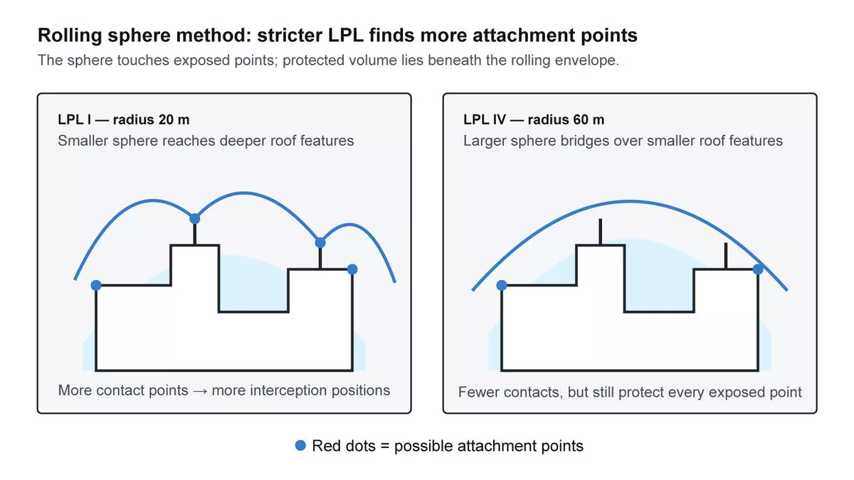
Figure 4 — The rolling sphere method: a smaller radius at a stricter protection level touches more of the structure and demands more air terminations.
That relationship is straight geometry, so you can put a number on it. For a vertical rod of height h standing on the surface being protected, with a sphere of radius r resting against it, the protected radius x at the base is:
`x = √(r² − (r − h)²)`
A 10 m rod at LPL III, where r is 45 m, protects a radius of √(2025 − 1225) ≈ 28,3 m. The same rod at LPL I, where r is 20 m, protects only √(400 − 100) ≈ 17,3 m. Same rod, same building, different protection level, and the covered area falls by roughly two thirds. Raising the rod recovers some of it, which is the trade every air-termination layout ends up making.
The mesh method suits flat roofs, where a conductor grid across the surface is more practical than a forest of rods. Mesh sizes run 5 m × 5 m at Class I, 10 m × 10 m at Class II, 15 m × 15 m at Class III and 20 m × 20 m at Class IV. Treat those as the design grid rather than as an absolute ceiling, and confirm them against your copy of IEC 62305-3. The 2024 edition rewrote the positioning clauses, simplified the main text and moved the detailed guidance into a new Annex D.
The protective angle method covers rods and masts, with the protected volume a cone below the tip. The angle is not a single value: it narrows as the air termination gets taller and as the protection level gets stricter, and IEC 62305-3 gives it as a curve in Figure 1 rather than a table. The method is also bounded by the rolling sphere radius for the level, so above 20 m at LPL I, 30 m at LPL II, 45 m at LPL III and 60 m at LPL IV it no longer applies and you use the rolling sphere instead. Read the angle off Figure 1 of IEC 62305-3 in the current edition; the curve was among the material reorganised in 2024, and a protective angle taken from an older reproduction is not worth the risk.
Step 4: down conductors and the earth termination
Down conductors carry the intercepted current from the air termination to earth. The goal at this stage of lightning protection system design is several parallel paths rather than one. More paths means less current per conductor, a smaller magnetic field inside the building, and a shorter route to ground.
IEC 62305-3 Table 5 sets preferred spacings between down conductors by class: 10 m at Class I, 10 m at Class II, 15 m at Class III and 20 m at Class IV. The word matters. The table is titled preferred values, not maximum values. The 2010 edition called them “typical preferred” and 2024 shortened it to “preferred”. You will find guides online quoting a 10/15/20/25 m sequence and calling those maximum spacings; that sequence does not match the IEC table, and if a project specification requires it, that requirement is coming from somewhere other than IEC 62305-3.
Conductor sizing in lightning protection system design traces back to the current parameters in Step 2. For the general above-ground case, meaning solid round air-termination conductors and down conductors, the minimum cross-sectional area is 50 mm² in copper, aluminium or steel. That single figure does not cover every case: IEC 62305-3 specifies by configuration as well as material, so tape, stranded conductor, plate and rod each carry their own minimum dimensions, and buried earth electrodes are specified by diameter and thickness rather than area alone. Check Tables 7 and 8 in Clause 5.6.2 for the configuration you are actually installing.
Material choice is as much a corrosion question as a conductivity one. IEC 62305-3 sets out LPS materials and their conditions of use in a table of its own, covering which materials suit which mounting surfaces and which environments. The conditions matter as much as the cross-section, because a conductor that corrodes through at a joint has stopped being a conductor regardless of how it was sized. Check the material, the surface it contacts, whether it is buried, and the compatibility of any dissimilar-metal joint and its fasteners against that table before specifying.
The earth termination disperses the current into the soil, and its resistance should be as low as the ground allows. Soil resistivity is the constraint, and it is one of the reasons IEC 62305-3 pushes the design earlier: access to the ground and the use of foundation steelwork “may well be impossible once construction work on a site has commenced”. Establish soil conditions at the earliest project stage, because the cheapest earth electrode is the one designed into the foundations.
One practical addition at this stage is a lightning strike counter on a down conductor. The Thor TRSC lightning counter mounts on 35 mm DIN rail and uses CT sampling, registering counts from 0 to 99 across 15–50 kA at 10/350 µs for Class I current and 5–100 kA at 8/20 µs for Class II. It changes maintenance from a calendar exercise into an evidence-based one: a system that has recorded strikes gets inspected on what it has actually taken, not on how long it has been standing. Figure 5 shows the supplied TRSC product photo; the image is illustrative of the counter form factor, not an installation claim.
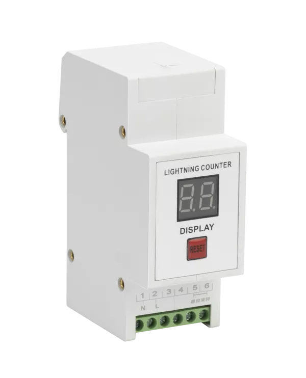
Figure 5 — Thor TRSC lightning strike counter for down-conductor monitoring.
Step 5: internal protection, zone boundaries and surge protection
An external system that intercepts a 100 kA stroke and dumps it into the earth electrode has done its job and created a new problem. That current couples into everything nearby. Cables, pipework and the electrical installation all see the field, and the equipment on the end of those cables has a withstand level measured in kilovolts, not tens of kilovolts.
IEC 62305 answers this by dividing the building into lightning protection zones. IEC 62305-1 defines them by the threat found in each:
| Zone | Threat |
| LPZ 0A | Direct flash and the full lightning electromagnetic field; internal systems can see full or partial surge current |
| LPZ 0B | Protected against direct flashes, but still the full electromagnetic field; internal systems can see partial surge currents |
| LPZ 1 | Surge current limited by current sharing and by isolating interfaces or SPDs at the boundary; spatial shielding attenuates the field |
| LPZ 2 and beyond | Current limited further by additional SPDs or isolating interfaces at each boundary |
The general rule of internal lightning protection system design is that equipment must sit in a zone whose electromagnetic characteristics it can actually withstand. That is the design principle in one sentence, and it turns the job from guesswork into a boundary question: every point where a conductor crosses into a lower-threat zone needs a suitable measure, chosen for that service and sized for the threat outside the boundary. Depending on the service, that measure is bonding, shielding, an isolating interface, an SPD, or some combination.
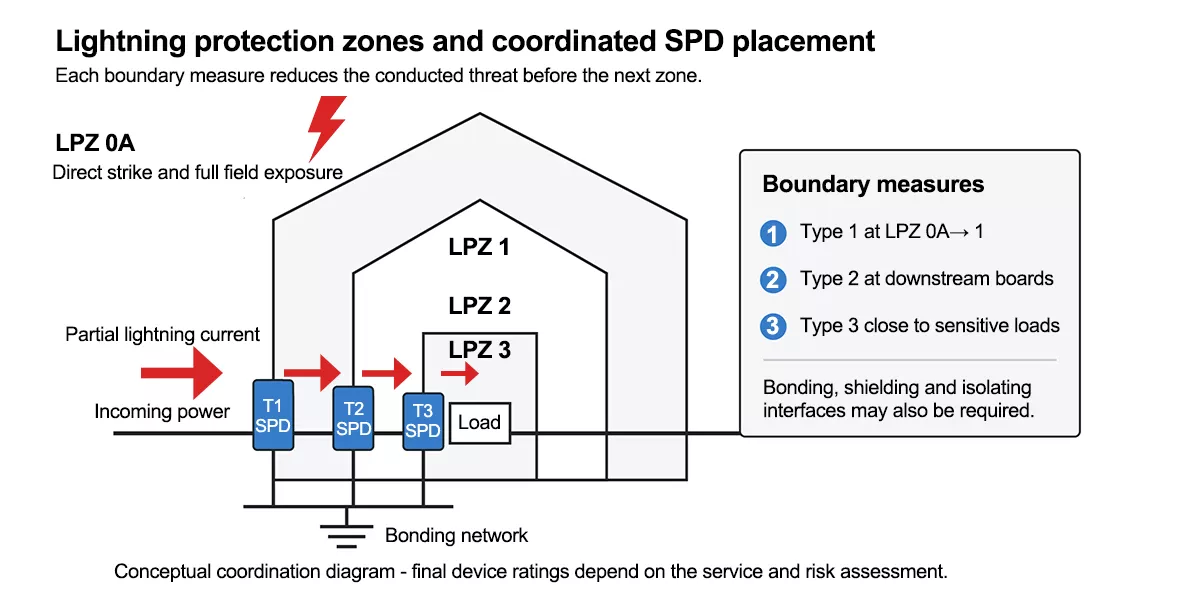
Figure 6 — Lightning protection zones through a building, the stage of lightning protection system design where SPDs sit at each boundary crossing and the surge current falls at every step.
At the LPZ 0A to LPZ 1 boundary, where the service entrance meets a building with an external LPS, partial lightning current is expected. That calls for a Type 1 SPD tested with the 10/350 µs impulse from Step 2, not a Type 2 device rated only for 8/20 µs. The Thor TRS-A series covers this position with graphite gap technology to EN 61643-11 Class I, at Iimp 15 kA, 25 kA and 50 kA with Up from ≤2,0 kV to ≤2,5 kV. The TRS-A25 sits in the middle of that range at Iimp 25 kA.
Figure 7 shows the supplied TRS-A25 product photo. The visible device label supports the model identification; final configuration and certification documents still need to be checked for the specified market.
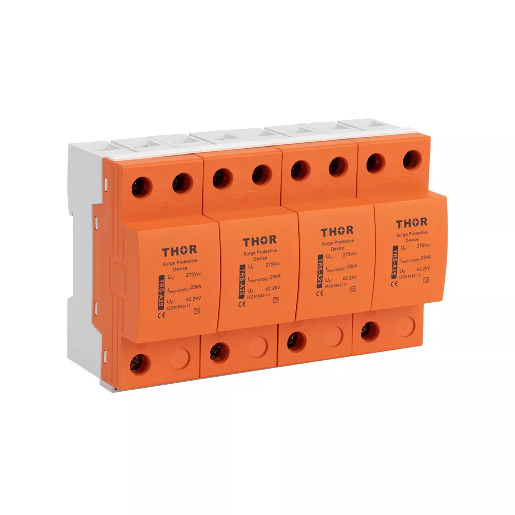
Figure 7 — Thor TRS-A25 Type 1 AC surge protective device.
One device at the entrance is rarely the finished job. The Up that a Type 1 SPD lets through is still well above what a control system tolerates, so downstream boundaries need their own devices with progressively lower let-through, coordinated so the upstream device takes the energy. Type 2 equipment belongs at those downstream boundaries. The TRSX Lightning Box, for instance, carries Type 2 modules from In 10 kA to 50 kA with Up between ≤1,5 kV and ≤2,5 kV in a wall-mounted enclosure, protecting L-PE and N-PE at Uc 385 V AC. A Type 2 device does not replace a Type 1 at an LPZ 0A boundary, where partial lightning current with a 10/350 µs waveform is expected. That is a design exercise in its own right, covered in our guides to the lightning protection zone concept and to SPD coordination. If you are still choosing between device classes, the Type 1 vs Type 2 vs Type 3 SPD comparison sets out where each belongs.
Figure 8 shows the supplied TRSX-100 enclosure photo, a real product example of the wall-mounted Type 2 form factor.
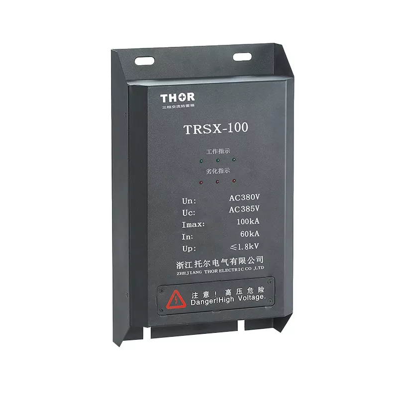
Figure 8 — Thor TRSX-100 wall-mounted Type 2 AC Lightning Protection Box.
Bonding does the other half of the work. IEC 62305-4 treats the bonding network, bonding bars and bonding at each zone boundary as part of the same system as the SPDs, because an SPD referenced to a poorly bonded earth has nothing solid to divert into.
What a lightning protection system will and will not do
Two misconceptions survive almost every conversation about lightning protection system design. A lightning protection system does not stop lightning, attract it, or reduce how often a building is struck. IEC 62305-3 states this directly in its introduction: the external LPS protects the structure by providing preferred attachment points and conducting and dispersing the current, and it “will not significantly influence the attachment process between the structure and the lightning to increase or reduce the number of direct lightning strikes to the structure”.
Both halves of that sentence get misread, and each misreading pushes a design the wrong way. Some readers assume a rod invites strikes that would otherwise miss. Others assume a protected building stops being hit. Neither is right. The strike count stays roughly the same. What changes is where the current attaches and where it goes afterwards.
No material stops a lightning flash either. Copper and aluminium are used because they carry very large currents briefly without melting, and the current parameters in Step 2 are what those cross-sections are sized against.
The other common misconception is about timing. An LPS is cheapest and most effective when it is designed with the structure, not added to it. IEC 62305-3 makes the point that foundation steelwork is often unusable as an earth electrode once construction has started, and that soil resistivity belongs in the earliest project decisions. Retrofits are entirely possible. They are simply more constrained, because less of the structure is available to work with.
Inspection and maintenance
Lightning protection system design does not end at handover. A finished lightning protection system design spends years doing nothing and then has to work once. Corrosion, mechanical damage, building alterations and modified services all degrade it quietly, so the design on paper drifts from the system on site, so IEC 62305-3 places inspection, testing and maintenance in its own clause, and national regulations can make those requirements mandatory.
Inspection covers the visible condition of air terminations, conductors and connections, plus earth resistance measurements and continuity of the bonding. IEC 62305-4 adds the internal side: a management plan, a defined inspection procedure and documented results. SPDs need particular attention because they age. A device that has absorbed surges may still be in place and still look installed while no longer protecting anything, which is why fault indication and remote signalling exist and why our SPD maintenance guide covers testing them properly.
Building work is a trigger for reassessment. A new rooftop plant room, a photovoltaic array or a relocated service entrance changes the collection area, the zone boundaries, or both, and with them the lightning protection system design. When the structure changes materially, the assessment from Step 1 no longer describes the building you have.
FAQ
What is lightning protection system design based on?
Lightning protection system design under IEC 62305 is based on a risk assessment, not on building type or floor area. IEC 62305-2 compares the calculated risk R against a tolerable risk RT. If the risk is too high, that assessment produces a lightning protection level from I to IV, which then sets the class-dependent design criteria including lightning current parameters, rolling sphere radius, mesh size and down-conductor spacing.
How do I calculate whether a building needs lightning protection?
Lightning protection system design starts the calculation with the equivalent collection area from IEC 62305-2 Annex A: AD = L × W + 2 × (3 × H) × (L + W) + π × (3 × H)² for a rectangular building on flat ground. The local ground strike-point density NSG is an input, but the annual dangerous-event number ND also needs the location factor CD and the km²-to-m² unit conversion. Then apply RX = NX × PX × LX for each risk component and compare the total against RT. A full lightning protection system design calculation also needs the probability and loss tables from the standard, which is why most practitioners run it in software.
What is level 4 lightning protection?
LPL IV is the least demanding of the four IEC 62305 protection levels. It is designed against a maximum first positive stroke of 100 kA and uses a 60 m rolling sphere radius with a 20 m by 20 m mesh. IEC 62305-1 puts the probability that lightning parameters stay within LPL IV limits at 0,95 on the maximum side and 0,84 on the minimum side, against 0,99 at both ends for LPL I.
Does a lightning rod attract more lightning to a building?
No. IEC 62305-3 states that an external lightning protection system will not significantly influence the attachment process to increase or reduce the number of direct strikes to a structure. An air termination gives the flash a preferred attachment point and a controlled path to earth, for a strike that was going to happen anyway.
Where do surge protective devices fit into a lightning protection system?
In lightning protection system design, SPDs sit at lightning protection zone boundaries, wherever a conductor crosses from a higher-threat zone into a lower-threat one. A Type 1 SPD tested with the 10/350 µs impulse belongs at the LPZ 0A to LPZ 1 boundary where partial lightning current is expected, with coordinated devices further downstream reducing the let-through voltage to something the connected equipment can withstand.
How often does a lightning protection system need inspecting?
IEC 62305-3 requires periodic inspection, testing and maintenance, and national regulations often set mandatory intervals, so the local requirement governs. Beyond the schedule, any material change to the building, such as a rooftop array, a new plant room or a relocated service entrance, is a trigger to revisit the original risk assessment and zone layout.
Thor Electric surge protection for lightning protection systems
Thor Electric manufactures the surge protective devices that complete a lightning protection system design to IEC 62305: Type 1 SPDs tested to the 10/350 µs impulse for service entrances with an external LPS, Type 2 and Type 1+2 devices for downstream boundaries, DC and PV ranges, signal-line protection, and the TRSX Lightning Box for wall-mounted installations. The AC ranges are designed to the applicable EN and IEC 61643-11 requirements, while certification and marking documents vary by series and by destination market, so ask for the documents covering the models you are specifying. OEM and ODM production is available, and samples can be supplied for evaluation against your own lightning protection system design and zone layout. Contact us with your protection level, system voltage and boundary positions for a device recommendation.