
A solar DC SPD connection diagram answers the one question every installer asks: how do you wire a surge protective device into the PV DC side without getting it wrong? The short answer is that the SPD sits in parallel between the live DC conductors and earth, and the correct configuration depends first on how the array is earthed, then on the system voltage.
Get the wiring right and the SPD clamps transient overvoltage before it reaches the inverter. Get it wrong, whether that is a series connection, a floating array on a two-pole device, or too much lead length, and the protection margin can fall away. Below is how to read the diagram, where to install the device and which Thor TRS3 configuration matches your system. For AC and three-phase layouts, our SPD wiring diagram guide covers the mains side.
How a solar DC SPD connects: the basic rule
A solar DC SPD connection diagram is simple at its core: the surge protective device connects in parallel between the PV+ and PV− conductors and protective earth, not in series with the string current. When a surge appears, the SPD becomes conductive and diverts that energy to earth, away from the inverter.
That parallel rule is the single point the DIY forums keep arguing about. String current never flows through the SPD in normal operation. The device conducts only during the surge, then returns to its high-impedance state. Draw it in series and you have created a fault, not a protection scheme.
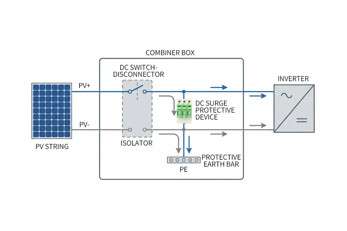
Figure 1 — Basic solar DC SPD connection: the surge protective device sits in parallel across PV+ and PV− to protective earth inside the combiner box, with the string current flowing straight through to the inverter.
Which solar DC SPD connection diagram is correct: earthing first, then voltage
The forum question “which of these two diagrams is right” has a real answer, and it starts with earthing, not voltage. A photovoltaic array sits one of two ways relative to earth, and that shapes how many poles the SPD has to protect.
On a functionally earthed array, one pole is bonded to earth, so overvoltage appears mainly between the live pole and earth, and a two-pole (U-type) connection covers that path. On an unearthed or floating array, either pole can swing against earth and a single insulation fault can push one pole toward full array voltage, so the safer choice is a Y-type, three-terminal connection where PV+ and PV− are each protected to a common earth terminal. IEC 61643-32 sets out both connection schemes and IEC 61643-31 requires the SPD to be rated for the earthing type it serves, with Ucpv on each mode of protection at least equal to the maximum PV open-circuit voltage. Confirm the connection against the SPD datasheet and the array design before wiring.
Thor’s own product coverage follows the same two configurations, ordered by voltage class. The table below lists the verified TRS3-C40 PV SPD options.
| Thor TRS3-C40 configuration | *Uocstc* | *Ucpv* | *Up* |
| U-type, two-pole | 500V DC | 600V DC | ≤2.0kV |
| U-type, two-pole | 600V DC | 720V DC | ≤2.3kV |
| U-type, two-pole | 800V DC | 960V DC | ≤3.0kV |
| Y-type, three-terminal | 1000V DC | 1200V DC | ≤4.0kV |
| Y-type, three-terminal | 1250V DC | 1500V DC | ≤5.0kV |
| Y-type, three-terminal | 1500V DC | 1800V DC | ≤6.0kV |
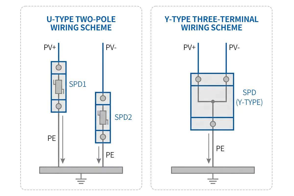
Figure 2 — U-type versus Y-type solar DC SPD connection diagram: a two-pole device for a functionally earthed array, and a three-terminal Y device for an unearthed or higher-voltage array.
Thor builds the TRS3-C40 in both the U-type (two-pole) and Y-type (three-terminal) body across its 500V to 1500V DC classes, all Type 2 to IEC 61643-31, so one PV Surge Protection Device line covers standard and higher-voltage PV arrays.
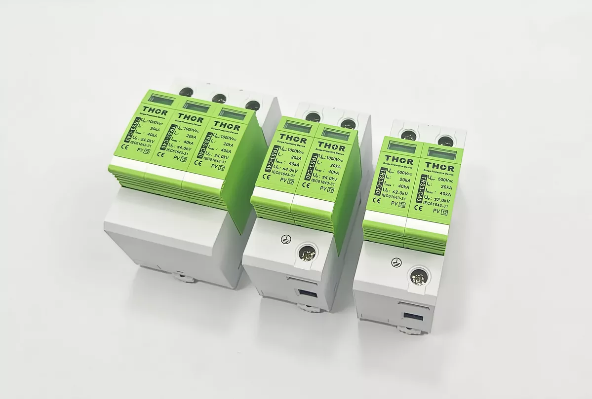
Figure 3 — Thor TRS3-C40 PV Type 2 SPDs: a three-pole (Y) 1000V unit alongside two-pole (U) 1000V and 500V units, each marked PV T2, IEC 61643-31, In 20kA and Imax 40kA.
Where to install a solar DC SPD
Placement decides how much of the SPD’s rating actually reaches the inverter. Two rules govern it: the 10-metre rule for how many devices you need, and where each device sits relative to the DC isolator.
The 10-metre rule is a distance check. When the cable run from the PV array to the inverter is under 10 metres, one DC SPD at the inverter DC input covers the whole path. When the run is longer than 10 metres, the induced surge on that cable can be large enough to need two devices: one at the array or combiner box, and one at the inverter input. A long outdoor DC loop picks up surge energy along its length, so protecting only one end leaves the other exposed.
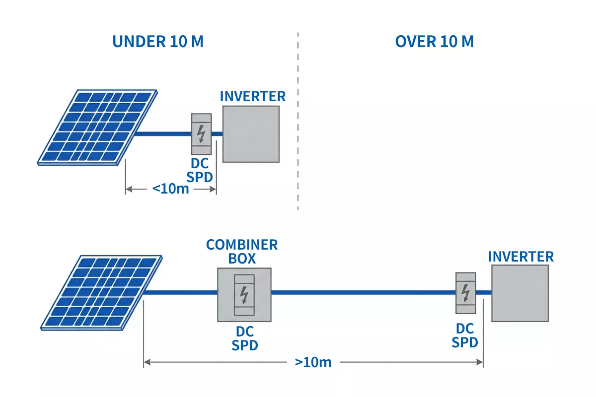
Figure 4 — The 10-metre rule: one DC SPD at the inverter DC input when the array-to-inverter run is under 10 metres, and two devices (one at the array or combiner box, one at the inverter) when it is longer.
Which side of each isolator the SPD lands on follows the combiner or inverter design and the manufacturer’s wiring diagram. The aim behind IEC 60364-5-53 is that the SPD keeps protecting through its own internal disconnector or a backup fuse rather than being switched out by a routine service isolator, because a surge can arrive while that isolator is open. Verify the exact arrangement against the standard and the equipment documentation for your installation.
| DC cable run (array to inverter) | Number of DC SPDs | Where they connect |
| Under 10 m | One | At the inverter DC input |
| Over 10 m | Two | One at the array or combiner box, one at the inverter input |
DC SPD vs AC SPD, and whether solar panels need one
Two questions come up together here, so treat them as two answers.
First, a DC SPD is not an AC SPD with a new label. A PV DC device is built and tested to IEC 61643-31 and rated by Ucpv, the maximum continuous DC voltage; an AC Surge Protection Device is built to IEC 61643-11 and rated by Uc. Direct current has no natural zero crossing, so the internal disconnection behaviour differs, and putting an AC SPD on the PV DC side is a dangerous selection error. For the wider type breakdown, see our Type 1 vs Type 2 vs Type 3 SPD guide.
Second, whether a PV array needs an SPD follows a risk assessment, not an automatic yes. The trigger points are a nearby lightning protection system, an exposed site, long outdoor DC cable runs, or a project specification that calls for it. IEC 61643-32 and IEC 62305 set out the risk method that weighs these factors, and the inverter DC input is worth protecting because it is expensive electronics wired straight to long outdoor conductors.
Choosing type and voltage for a PV DC SPD
With the connection settled, two ratings finish the selection: type class and Ucpv.
Type 2 covers induced surges and switching transients, the exposure on a standard rooftop or commercial array without a direct lightning-current path. Type 1+2 comes in when the DC side can see partial lightning current, typically a building with a lightning protection system where the array cannot hold the separation distance. Thor covers both with the TRS3-C40 Type 2 and the TRS3 High Type 1+2 module; the surge protection device for solar panels guide walks through matching them to array layout.
Voltage selection turns on one figure: Ucpv must be equal to or greater than the maximum PV open-circuit voltage under the coldest expected conditions, not the inverter’s nominal DC voltage. Cold weather raises string Uoc, so a 1000V nominal array can climb well past 1000V at dawn in winter. Take the module Voc temperature coefficient from its datasheet, correct for your site’s minimum design temperature, and pick a Ucpv class above that number.
A hypothetical example makes the margin concrete. Take a 1000V array built from modules with a Voc temperature coefficient of −0.3%/°C, on a site whose minimum design temperature is −10°C. That is 35°C below the 25°C rating point, so Voc climbs by about 0.3% × 35 = 10.5%. A string sitting near 1000V open-circuit at standard test conditions then reaches roughly 1105V cold. A 1000V Ucpv device has no headroom left, so a 1200V Ucpv class satisfies the voltage condition in this example. The inputs here are hypothetical; run the calculation from your own module datasheet and design temperature.
The TRS3-C40 spans 600V to 1800V Ucpv, so a design margin is available at each PV class, including the common 1000V and 1500V systems. We rate the TRS3-C40 across the line to Iscpv 10kA, a short-circuit figure that matters on the DC side, where fault behaviour differs from an AC circuit.
Wiring details that decide real protection
A correctly chosen SPD still fails if the connection work is sloppy. Four details carry most of that risk.
Figure 5 — A representative rooftop solar PV installation: grid-tie inverters feeding a distribution and protection box, the kind of enclosure where a DC SPD is wired in alongside the breakers and metering.
Lead length is the big one. Under IEC 60364-5-53, the total connecting length of an SPD, the loop from the live conductors through the device to the earth conductor, should be kept as short as possible and preferably under about 0.5 m. The physics is V = L·di/dt: every extra centimetre of lead adds inductance, and a fast surge turns that inductance into voltage the inverter still sees, on top of the SPD’s rated Up. A neatly routed but long loop can defeat a good device.
The other three are quick checks. Earth conductor cross-section for a Type 2 SPD is at least 6 mm² copper under IEC 60364-5-53. Backup fusing on the DC side follows the gPV rules of IEC 60364-7-712. And status visibility matters where the array is hard to reach: the TRS3 modules carry a visual fault window plus an optional remote signalling contact rated 250V/0.5A AC, which flags a spent cartridge to a monitoring system. The TRS3 terminals accept 16 mm² solid or 35 mm² stranded conductor, which is terminal capacity rather than a required cable size; the actual conductor follows the installation design. The pluggable module also swaps out without rewiring, so a spent cartridge is replaced without disturbing the connections.
Solar DC SPD pre-energisation checks
Run these checks before energising the DC side; each maps to a failure mode covered above.
- Confirm the SPD is wired in parallel across PV+, PV− and earth, not in series with the string.
- Confirm the device is a PV DC unit to IEC 61643-31 with a Ucpv at or above the array’s calculated cold maximum Uoc, not an AC SPD.
- Confirm the configuration matches the array: two-pole (U-type) for a functionally earthed array, three-terminal (Y-type) for an unearthed array.
- Confirm the connecting loop is short, ideally under about 0.5 m, with no large wiring loop around the enclosure.
- Confirm a second SPD is fitted at the far end when the array-to-inverter run passes 10 metres.
- Confirm the status indicator reads normal and any remote contact is wired back to monitoring.
FAQ
How is a solar DC SPD connected in a PV system?
A solar DC SPD connection diagram shows the device wired in parallel between the PV+ and PV− conductors and protective earth, never in series with the string current. On a functionally earthed array a two-pole (U-type) connection is used; on an unearthed or floating array a three-terminal Y-type connection protects both poles to earth.
What is the difference between an AC SPD and a DC SPD?
A DC SPD is tested to IEC 61643-31 and rated by Ucpv; an AC SPD follows IEC 61643-11 and is rated by Uc. Direct current has no natural zero crossing, so an AC SPD must never sit on the PV DC side.
Do solar panels need a surge protection device?
It depends on a risk assessment, not a blanket rule. A PV array needs DC surge protection when there is a nearby lightning protection system, an exposed location, a long outdoor DC cable run, or a project specification requiring it. IEC 61643-32 and IEC 62305 set out the method that weighs these factors.
Should the DC SPD go in the combiner box or at the inverter?
Both, depending on distance. Under a 10-metre array-to-inverter run, one SPD at the inverter DC input is enough; over 10 metres, add a second at the array or combiner box.
Do I need a Type 2 or Type 1+2 DC SPD for my PV array?
Type 2 suits rooftop and commercial arrays exposed to induced surges and switching transients. Type 1+2 is for arrays that can carry partial lightning current, such as a building with a lightning protection system where the separation distance cannot be held.
What Ucpv should a 1000V solar DC SPD have?
Ucpv must sit above the array’s maximum open-circuit voltage at the coldest expected temperature, not the nominal 1000V. Calculate the cold Uoc from the module datasheet coefficient, then choose a Ucpv class at or above that value; for many 1000V arrays that lands in the 1200V class.
Thor Electric PV DC surge protection
Thor Electric manufactures PV DC surge protective devices to IEC 61643-31: the TRS3-C40 Type 2 in U-type (two-pole) and Y-type (three-terminal) bodies across 500V to 1500V DC classes, and the TRS3 High Type 1+2 module in the Y configuration for LPS-connected rooftop arrays. Thor’s SPD range carries IEC, TUV and CE certification. Samples, custom voltage configurations and OEM production are available. Contact our team to match a DC SPD to your PV array.