
A lightning protection system does not attract lightning and cannot stop a strike. It gives the strike a controlled low-impedance path to earth, prevents it from sparking across to nearby metal inside the building, and limits the residual surge that reaches electrical equipment. IEC 62305 assigns those jobs to separate protection layers. Skip any one layer and the system has a gap that lightning will find.
The guide below covers a complete lightning protection system for commercial and industrial buildings: external strike interception, internal equipotential bonding, coordinated surge protective devices, and the IEC zoning framework that ties them together.
What is a lightning protection system?
A lightning protection system (LPS) intercepts a lightning strike, conducts the current to earth, and limits the electrical effects inside the building. IEC 62305 defines three layers: the external LPS (air terminals, down conductors, earthing), internal lightning protection (equipotential bonding and separation distance), and LEMP protection with coordinated surge protective devices. A complete design considers all three layers.
A complete system covers two threats: the strike path through the structure and the residual surge entering electrical equipment. The external hardware intercepts the strike and carries kiloampere-level current to ground. Internal measures stop that current from jumping across to pipes, cable trays, or steelwork through a sideflash. Coordinated SPDs at each zone boundary limit the residual transient voltage for downstream equipment.
How a lightning protection system works
When lightning hits a building with an external LPS, the air termination network (rods, masts, or a mesh of horizontal conductors on the roof) captures the strike. The current flows down multiple parallel down conductors attached to the building facade and into the earthing system buried below grade. The external path has one job: direct the current into the soil and away from combustible materials.
The second job starts immediately. A lightning strike generates steep voltage gradients along the down conductors, and without countermeasures, the potential difference between the LPS and nearby metal services (water pipes, gas lines, cable trays, structural steel) can arc across the gap. IEC 62305-3 counters this with equipotential bonding and by maintaining a calculated separation distance between the LPS conductors and internal metalwork. Together, bonding and separation reduce the sideflash risk to an acceptable level.
The third job is electrical. Even after the external LPS dissipates the main strike current, induced surges and conducted transients travel into the building along power, data, and signal cables. As the IET guidance on surge protective devices explains, the external LPS does not remove the need to protect the electrical installation from transient overvoltages. IEC 62305-4 calls the lightning-related electromagnetic threat LEMP (lightning electromagnetic impulse) and uses the LPZ concept with coordinated surge protection measures selected for the threat at each boundary. Figure 1 maps the full current path and all three layers.
| Layer | Components | What it does | What it prevents |
| External LPS (IEC 62305-3) | Air terminals, down conductors, earthing electrodes | Intercepts the strike, conducts current to earth | Fire, structural damage, direct current through building |
| Internal lightning protection (IEC 62305-3) | Equipotential bonding bars, separation distance | Equalizes potential between LPS and metalwork | Sideflash arcing, insulation breakdown |
| LEMP protection (IEC 62305-4) | Coordinated SPDs selected for each boundary | Clamps residual surge voltage at zone boundaries | Equipment damage from conducted/induced transients |
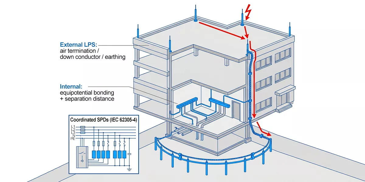
Figure 1 — Complete lightning protection system showing the external current path (air terminals, down conductors, earthing) and the internal layers (equipotential bonding bar and coordinated SPDs at the service panel).
The external LPS: air terminals, down conductors and earthing
The external LPS is the physical hardware that intercepts the strike and moves the current to ground. IEC 62305-3 defines three placement methods for air terminals: the rolling sphere method, the mesh method, and the protective angle method. Each uses different geometric logic to define the capture zone for the lightning channel, and IEC 62305-3 permits any of them subject to the height and geometry conditions defined in the standard.
Air termination
The rolling sphere method imagines a sphere of a specific radius rolling over the structure. Any point the sphere touches is exposed and needs an air terminal. The sphere radius varies by protection class, and it drives every other design parameter:
| LPS class | Rolling sphere radius | Mesh size | Max down-conductor spacing |
| I | 20 m | 5 m × 5 m | 10 m |
| II | 30 m | 10 m × 10 m | 10 m |
| III | 45 m | 15 m × 15 m | 15 m |
| IV | 60 m | 20 m × 20 m | 20 m |
A smaller sphere radius (Class I) means more air terminals and tighter spacing. Class I is the most protective; Class IV is the least. The mesh method lays a grid of horizontal conductors on the roof, with mesh dimensions matching the table above. The protective angle method uses a height-dependent cone of protection that narrows as the air terminal gets taller; for tall structures the usable angle becomes very small, which is why taller buildings typically rely on the rolling sphere or mesh approaches.
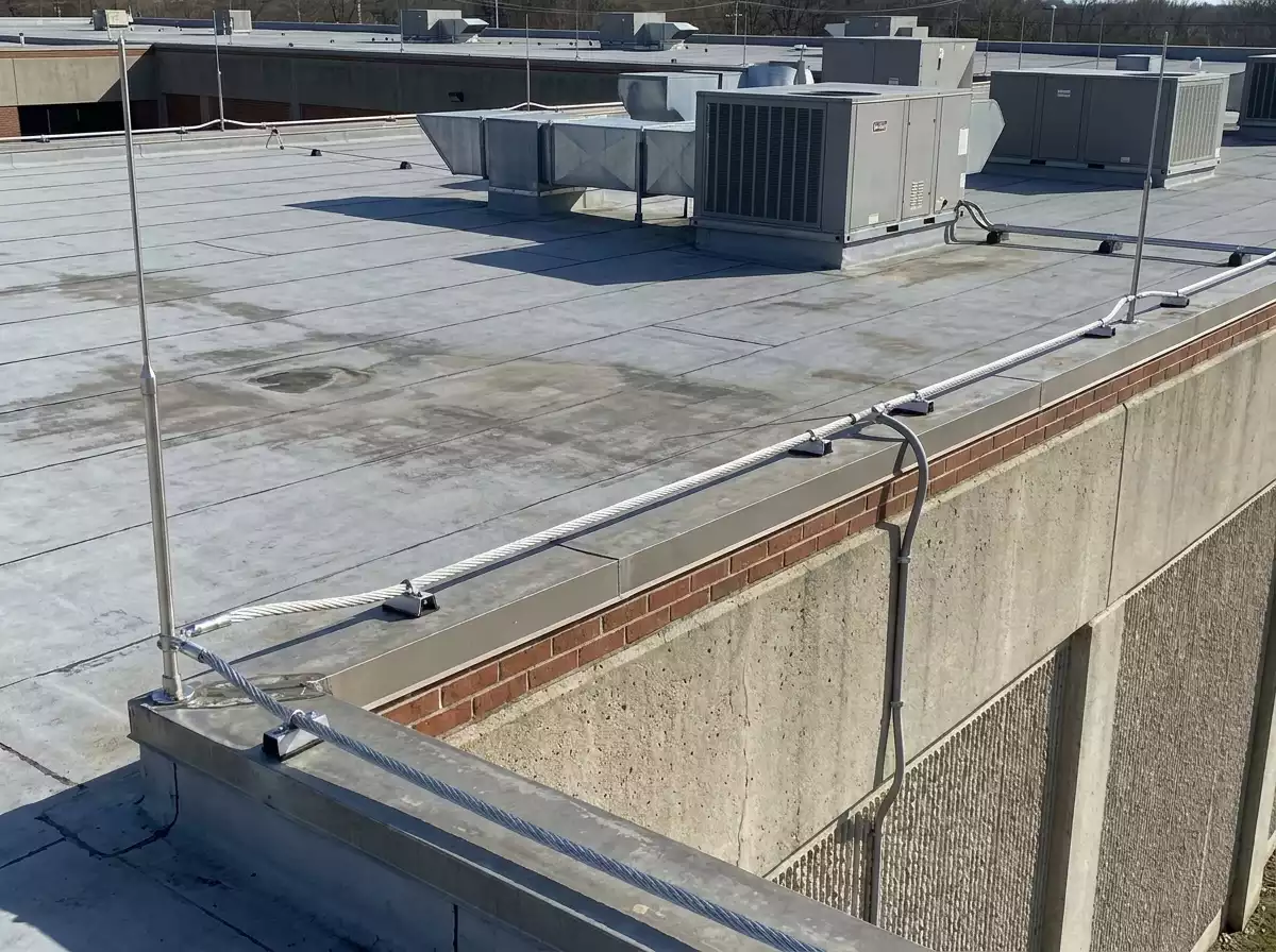
Figure 2 — Commercial rooftop with air terminals and a visible down conductor forming the external lightning protection path.
Down conductors
Down conductors carry the strike current from the air terminals to the earthing system. IEC 62305-3 requires a minimum of two down conductors distributed around the building perimeter. For larger structures, the count is set by dividing the perimeter by the maximum spacing for the protection class (10 m for Class I/II, 15 m for Class III, 20 m for Class IV) and rounding up.
Minimum conductor cross-sections by material:
| Material | Air termination and down conductors | Earth electrodes |
| Copper | ≥ 50 mm² | ≥ 50 mm² |
| Aluminium | ≥ 70 mm² | Not permitted (corrosion) |
| Galvanized steel | ≥ 50 mm² | ≥ 80 mm² |
Mixed-metal connections need compatible fittings or bimetallic connectors to limit galvanic corrosion between copper, aluminium, and steel.
Earthing
IEC 62305-3 defines two earthing arrangements. A Type A arrangement uses individual earth electrodes (rods or plates) connected to each down conductor separately. A Type B arrangement uses a ring earth electrode buried around the building perimeter, or the foundation reinforcement itself as a natural earth electrode. Type B is often selected for larger commercial and industrial structures.
One widespread misconception: IEC 62305-3 mandates a 10 Ω earth resistance target. It does not. The standard specifies electrode geometry and dimensions, not a fixed resistance value. The 10 Ω figure appears in some national annexes and design guides as a practical rule of thumb, but it is not a normative IEC requirement. Earthing design is always site- and soil-dependent.
Lightning protection zones: the framework that ties it together
The lightning protection zones (LPZ) framework from IEC 62305-4 divides a building into nested zones based on the electromagnetic and current exposure at each boundary.
LPZ 0A is the area where a direct strike can land and the full lightning current flows. The roof surface and any unshielded external area fall here. LPZ 0B is shielded from direct strikes by the air-termination network but still exposed to the full external electromagnetic field. LPZ 1 is the building interior, where the external LPS and building shell reduce both current and field. LPZ 2 and LPZ 3 are progressively deeper internal zones (an equipment room, a shielded cabinet) with lower exposure still.
At each zone boundary, the surge threat steps down, and the SPD installed there must match the remaining threat. A Type 1 SPD is typically installed at the origin of an installation exposed to partial lightning current. Type 2 SPDs are used at distribution boards to limit the remaining transient overvoltage. Where the design assessment requires closer protection for sensitive equipment, point-of-use protection may be added farther downstream. Figure 3 shows one common coordinated arrangement; the final device selection depends on the installation and risk assessment.
The zone-to-SPD mapping is the backbone of coordinated surge protection. Without it, an SPD is a device bolted to a panel with no design rationale behind its rating or placement. With it, the engineer can trace the let-through energy from the origin of the installation to the final load and verify that each stage holds.
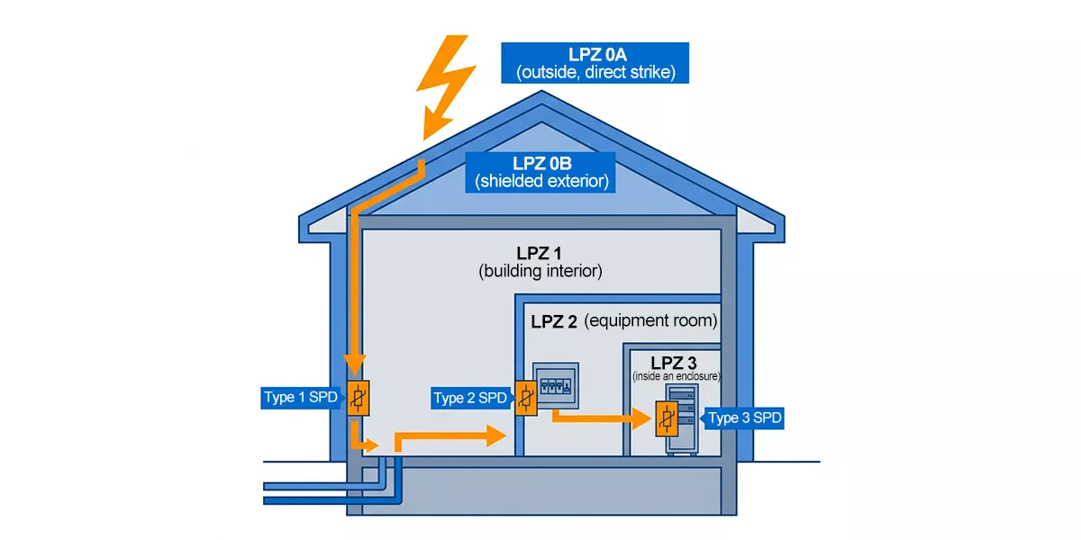
Figure 3 — IEC 62305 lightning protection zones from LPZ 0A (direct-strike exposure) through LPZ 3 (innermost enclosure), with SPD types at each boundary.
Sizing the system: risk assessment, protection level and rolling sphere
Risk assessment under IEC 62305-2
Before an LPS is designed, a risk assessment determines whether one is needed at all and, if so, how protective it must be. IEC 62305-2 formalizes this. The inputs fall into four categories: the physical characteristics of the structure (height, footprint, materials, roof geometry), the local environment (geographic flash density, terrain, nearby structures), the nature of what is inside (people, services, irreplaceable data, explosive or flammable materials), and the acceptable consequences of a lightning event (service interruption, equipment loss, life safety).
The assessment determines whether protection is required and at what level. If the calculated risk exceeds the tolerable threshold, the design uses an LPL from I (highest protection) to IV (lowest). That LPL then feeds into the design tables for rolling sphere radius, mesh dimensions, and down-conductor spacing.
Protection levels and the rolling sphere
The four protection levels correspond to four rolling sphere radii: 20 m (LPL I), 30 m (LPL II), 45 m (LPL III), and 60 m (LPL IV). A tighter LPL means more air terminals, closer down-conductor spacing, and finer mesh. The jump from Class III to Class I is a serious material and labour multiplier, which is why the risk assessment matters: over-specifying wastes budget, under-specifying leaves gaps. Figure 4 compares the four radii side by side.
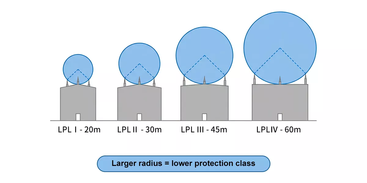
Figure 4 — IEC 62305 rolling sphere radii for each lightning protection level, from 20 m (LPL I, strictest) to 60 m (LPL IV).
Internal protection: bonding, separation distance and SPD coordination
The external LPS intercepts the strike and conducts its current to earth. Internal protection controls sideflash and residual surge energy.
Equipotential bonding
Metallic services entering the building connect to a common bonding point, either directly, through an SPD, or through a suitable spark gap depending on the service and local requirements. Without the correct bonding method, a potential difference can build between the LPS and an unbonded pipe or tray, allowing current to arc across the gap. That arc is a sideflash. It can start fires and damage insulation.
Separation distance
Where direct bonding is not practical (because an air gap or insulation must be maintained between the LPS and internal metal), IEC 62305-3 requires a minimum separation distance s to prevent flashover:
s = ki × (kc / km) × l
Here ki depends on the protection level, kc reflects how the lightning current distributes across the available down conductors, km accounts for the insulating material between the LPS and the metalwork (air = 1.0), and l is the length along the LPS conductor from the bonding reference point to the location being checked. The exact coefficient values and application conditions come from the relevant IEC 62305-3 design tables.
Coordinated SPDs
After the external path, bonding and separation distance are set, power and data cables can still carry conducted and induced surge energy. IEC 62305-4 calls for coordinated SPDs across LPZ boundaries.
Each SPD type in a Type 1 vs Type 2 vs Type 3 SPD arrangement has a specific job. Type 1 is typically installed at the origin of an installation exposed to partial lightning current and is tested with the 10/350 µs waveform. Its key rating is Iimp. Type 2 is installed at distribution boards and clamps the residual 8/20 µs surge, rated by In and Imax. Type 3 is point-of-use protection for sensitive equipment and is only added where the design requires it. Figure 5 shows a common coordinated arrangement rather than a mandatory three-device layout for every project.
The main SPD ratings answer different selection questions:
| Rating | What it tells the specifier |
| Iimp | Type 1 lightning-current capacity, tested with the 10/350 µs waveform |
| In | Type 2 nominal discharge current, tested with the 8/20 µs waveform |
| Imax | The maximum Type 2 discharge current under the 8/20 µs test |
| Up | The voltage protection level passed downstream during the test |
| Uc | The maximum continuous operating voltage the SPD can withstand |
SPD coordination requires compatible voltage protection levels and surge-energy capability between stages. Installation distance, decoupling impedance, and manufacturer coordination data also affect how the cascade shares the surge.
We use graphite gap technology across the TRS-A line for the Type 1 duty. The TRS-A series (15, 25, and 50 kA Iimp at 10/350 µs) responds in under 100 ns and is rated for lightning-current duty at the origin of the installation. For the Type 2 stage, the TRS-D, TRS-C, and TRS-B series cover 10 kA to 100 kA Imax (8/20 µs). The TRSX Lightning Box is an integrated wall-mount Type 2 enclosure rated Un 380 V AC, with models up to 100 kA Imax.
Where both a Type 1 lightning-current duty and a Type 2 limiting duty are needed at a single installation point, the TRS5-B+C and TRS8-B+C combined Type 1+2 devices combine both classifications in one module. They do not automatically remove the need for downstream coordination where the design assessment requires it.
Thor’s current AC surge protection device range covers Type 1, Type 2, and combined Type 1+2. Type 3 is an SPD classification but is not part of Thor’s product line at this time. A lightning strike counter like the TRSC can be fitted to the down-conductor path to log events for maintenance records.
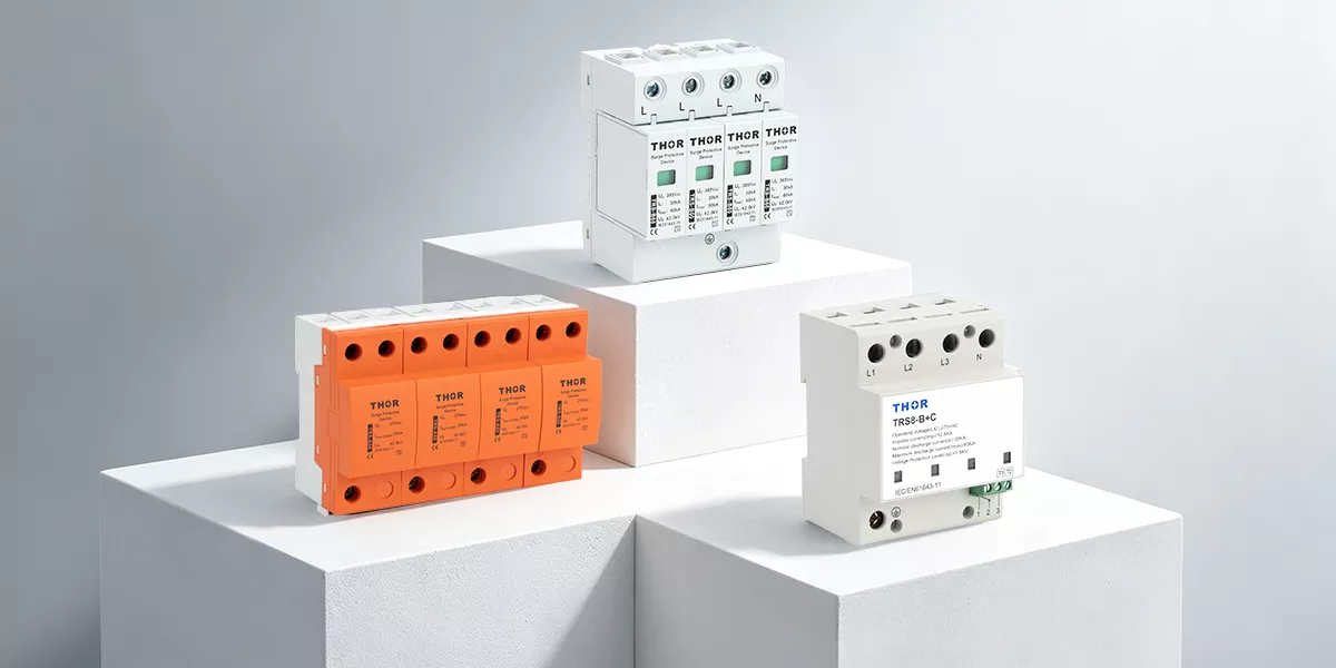
Figure 5 — Thor AC surge protection devices for Type 1, Type 2, and combined Type 1+2 applications.
The supply-system earthing arrangement (TN-S, TN-C-S, TT, IT) affects how SPDs connect across line, neutral, and earth. A TN-S earthing system with separate neutral and protective earth conductors typically uses a 3+1 or 1+1 SPD configuration. Getting this wrong changes the protection mode and can leave a path unprotected.
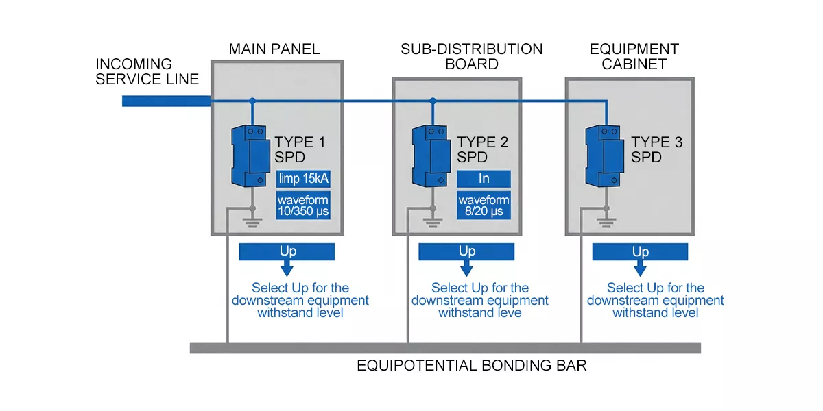
Figure 6 — Common coordinated SPD arrangement from the origin of the installation to sensitive equipment.
At a distribution board, the Type 2 stage can use DIN-rail modules or a wall-mount enclosure, depending on the panel layout and incoming supply arrangement. The device form does not replace the coordination checks shown above.
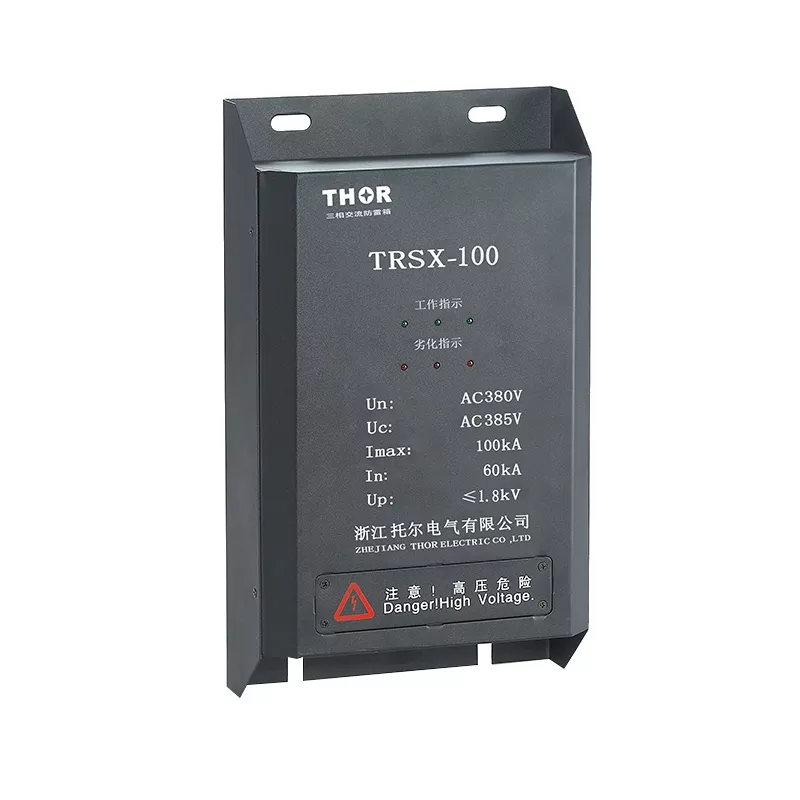
Figure 7 — Thor TRSX Lightning Box, a Type 2 wall-mount SPD enclosure for distribution board installations.
What drives lightning protection system cost and design complexity
There is no single price for a lightning protection system. The cost is driven by site-specific variables that interact:
Building geometry is the starting point. A taller building with a larger footprint needs more air terminals, longer down-conductor runs, and more earthing material. Complex roof shapes (multiple levels, parapets, towers) add conductor routing and bonding points.
The required protection level multiplies every line item. Moving from LPS Class IV to Class I tightens the mesh from 20 m to 5 m, cuts down-conductor spacing from 20 m to 10 m, and increases the minimum conductor count. For a medium-sized industrial building, the material and labour difference between Class III and Class I can be significant.
Rooftop equipment adds complexity. Photovoltaic arrays, HVAC units, antenna masts, and exhaust stacks may require bonding or an isolated air-termination arrangement, depending on the calculated separation distance. For PV installations, see our solar surge protection guide for the DC-side SPD requirements.
Earthing and soil conditions are a less visible cost driver. High-resistivity soils (rock, sand, dry clay) may require longer electrode runs or additional rods. Integrating a new LPS earthing arrangement with an existing plant earth grid adds coordination work.
Internal SPD coordination adds a separate line item for each relevant zone boundary. The number of incoming supplies, sub-distribution boards, incoming signal lines, and critical loads determines how many SPDs are needed and at what ratings. Sites with more zone boundaries and critical services require a wider coordination scope.
To get a meaningful quote, a supplier needs: the building drawings (plan and elevation), the required LPS class from the risk assessment, a list of services entering the building, the earthing arrangement and soil resistivity data, and the internal load inventory that defines the SPD coordination scope.
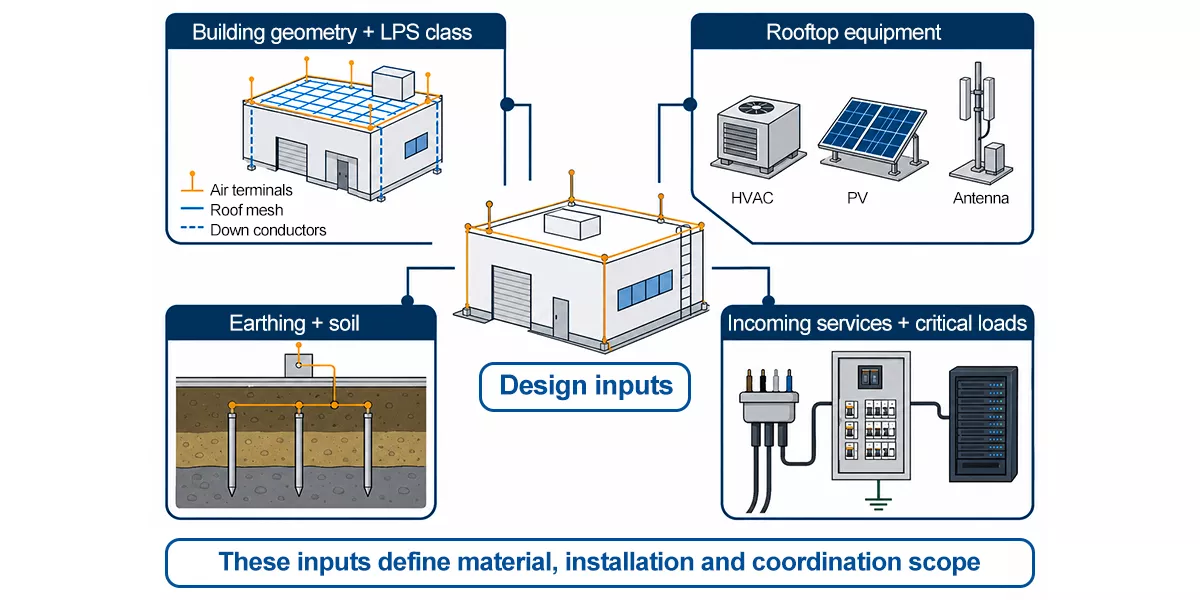
Figure 8 — Design inputs that determine lightning protection system scope: building geometry and LPS class, rooftop equipment, earthing conditions, and incoming services or critical loads.
Standards, compliance and whether it all works
Do lightning protection systems work?
A lightning protection system works when its conductors and bonding remain intact, its maintenance is current, and its selected SPDs limit surge energy reaching equipment. Low-impedance paths carry current preferentially, while SPDs limit transient voltage for downstream equipment. An external LPS without coordinated internal SPDs leaves electrical systems exposed. SPDs without proper bonding or separation distance leave the sideflash risk open.
Inspection should cover the condition of conductors and bonding connections, the visual fault indicators on SPDs, and remote signaling where fitted. A pluggable module showing a fault can be replaced without rewiring its base. TRSC lightning-counter records can support post-event checks, and any roof or service modification should trigger a review of the original design.
IEC 62305 and NFPA 780
IEC 62305 is the global standard framework. It covers the full scope in four parts: general principles (Part 1), risk assessment (Part 2), physical protection and internal measures (Part 3), and protection of electrical and electronic systems against LEMP with coordinated SPDs (Part 4). The LPZ zoning concept and systematic SPD cascade originate here.
NFPA 780 is the US structural lightning protection standard. It covers air terminals, down conductors, bonding, and earthing in depth, while applicable national codes and product standards set US electrical requirements. NFPA 780 does not define the IEC LPZ framework.
IEC 62305 is widely used for projects outside the United States, often through national adoptions or annexes. The engineer still needs to confirm the adopted standard and local code for the project location.
Thor Electric AC SPD series are designed to the applicable IEC 61643-11 and EN 61643-11 requirements. Certification and marking documentation varies by series; confirm the required TUV, CB, CE and RoHS documents for the selected model and destination market.
Related guides
The article covers the complete lightning protection system. For deeper treatment of specific areas:
- Telecom and data lines: signal surge protection devices
- Installation and wiring: SPD wiring diagram
FAQ
What is a lightning protection system in one sentence?
A lightning protection system is a combination of air terminals, down conductors, earthing electrodes, equipotential bonding, and coordinated surge protective devices that gives a lightning strike a controlled path to ground and limits the electrical effects on the building’s internal systems. IEC 62305 is the international standard framework that defines how these components work together.
What are the “three types of lightning protection systems”?
The phrase is ambiguous. It can mean three different things: the three IEC 62305-3 air-termination placement methods (rolling sphere, mesh, and protective angle), the classification of a complete LPS by protection level (Class I through IV, which is four, not three), or the three SPD types (Type 1, Type 2, Type 3) in the internal surge protection cascade. These are separate concepts. The air-termination methods describe how you position rods on a roof. SPD types describe how you coordinate surge devices across zone boundaries inside the building.
How does IEC 62305 differ from NFPA 780?
IEC 62305 is a four-part international framework covering risk assessment, structural protection, and coordinated SPD cascade design using the LPZ zoning concept. NFPA 780 is a US standard focused on structural lightning protection under the US code framework. For any location, check the adopted national standard and local code before design.
Does a lightning protection system need surge protection devices?
Yes. The external LPS intercepts the strike current and conducts it to earth, but induced surges and conducted transients still travel into the building on power and data cables. Without coordinated SPDs at the relevant boundaries, the electrical systems remain exposed to transient overvoltage even when the structural protection is in place. IEC 62305-4 covers this through the LEMP protection concept and coordinated surge protection measures selected for the installation.
Can one combined Type 1+2 SPD replace a full cascade?
A combined Type 1+2 device is rated for both the lightning-current (10/350 µs) and surge-limiting (8/20 µs) duties at a single installation point. It does not automatically replace downstream coordination. Where the design assessment shows deeper-zone protection is needed, downstream Type 2 or suitable point-of-use protection brings the voltage protection level closer to the equipment withstand level.
Does an existing building need a full lightning protection system retrofit?
It depends on the risk assessment. IEC 62305-2 evaluates the structure, environment, contents, and consequences to determine whether protection is needed and at what level. An existing building may need only internal SPD coordination added to the electrical system, or it may need a full external LPS plus bonding and an SPD cascade. The assessment drives the scope.
Thor Electric surge protection for lightning protection systems
Thor Electric manufactures the SPD portion of a lightning protection system: Type 1 (TRS-A series, graphite gap), Type 2 (TRS-B/C/D series and the TRSX Lightning Box), and combined Type 1+2 (TRS5-B+C, TRS8-B+C). The AC SPD series are designed to the applicable IEC 61643-11 requirements; certification and marking documents vary by series, and Uc is customizable on the TRS-A and TRS-B/C/D series. Samples, OEM, and ODM are available. Contact us to discuss your project requirements.